No.103 Have I missed the point – CDUs with Peco solenoids
I recently added my two-pennies-worth to an RMweb question about motorising Peco points. As a consequence and after some thirty years of playing with model trains I have now installed a couple of Capacitor Discharge Units (CDUs). What do I think? Well I have mixed feelings.
First some pictures (scanned images) going back in time to
earlier layouts.
Control panels with push buttons Bracken Ridge
This was the Bracken Ridge layout from the early 1980s. I
cannot remember but I don’t think model railways had heard of CDUs in the early
80s. Certainly I didn’t use a CDU and the Peco solenoids attached to my points
were operated by momentary contact switches wired in parallel directly from the
16v auxiliary AC supply from my Hammant and Morgan controllers.
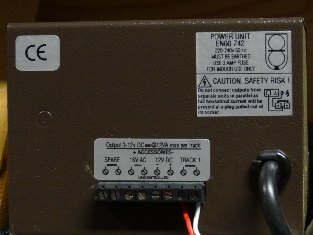
Control panel Park View NB Hi-tech wire connectors to
controller
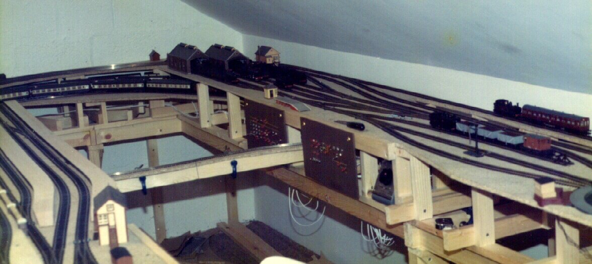
By the 1990s we had moved house and all the track, point
motors and switches were reused in the new Park View layout. Again it never
occurred to me nor did I find it necessary to use a CDU. The point motors, up
to two at a time, were operated directly from the 16v auxiliary AC supply.
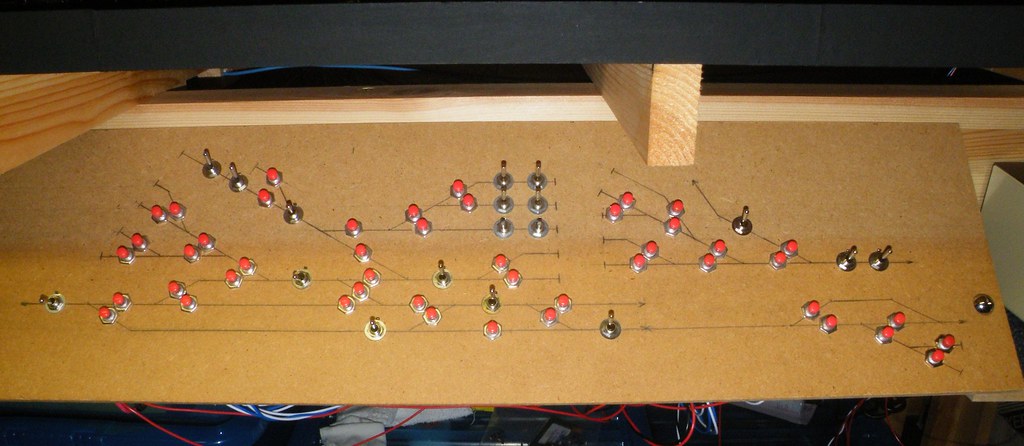
Current panel, front
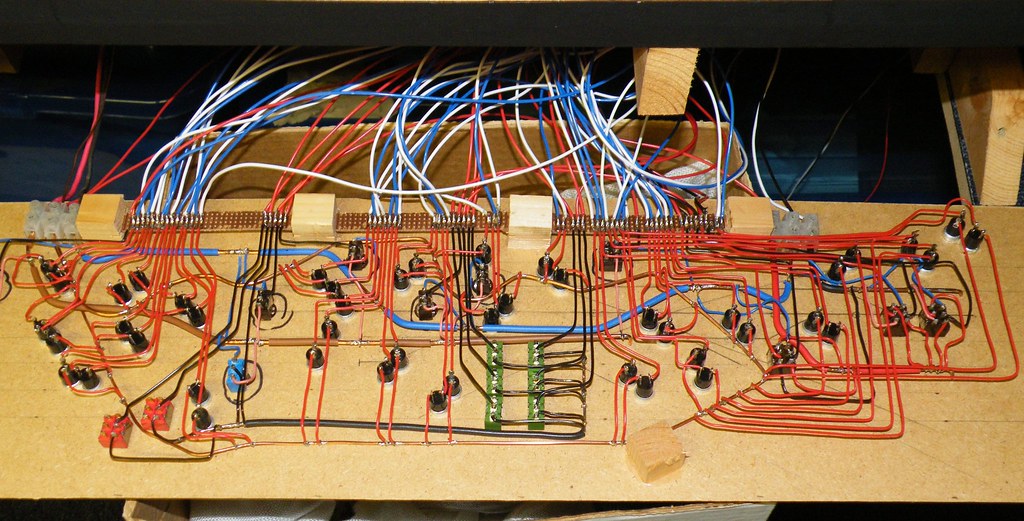
Current panel, rear
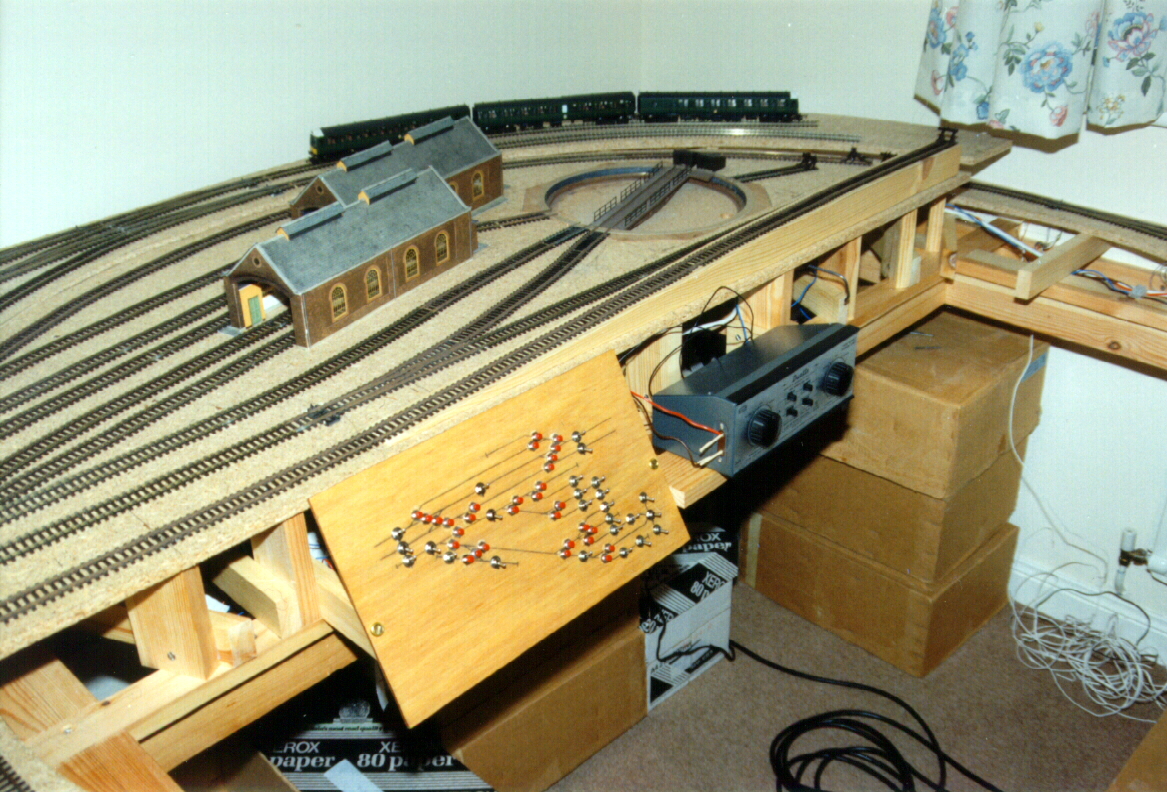
Move forward to 2007 and the start of construction of the
current layout. The same momentary contact switches were reused along with the
original Peco point motors. All the old small radius points were replaced by
new large radius points but the original solenoids were retained. The system
has been expanded, but this has been done by adding to the original rather than
by replacement. As a result the current control panels contain a selection of
the original momentary contact switches from the late 1970s. Yes some point
motors buzz but the points all operated.
Have there been any problems? Well yes, operation of the
Peco 3-way point has been an issue. The 3-way point on the two early layouts
was the Insulfrog version which simply required two solenoid motors. The
current 3-way points are both Electrofrog which require two solenoids each
fitted with a Peco changeover switch. I sense that the operation is at the
limit of my system. I have had to replace two or three momentary contact
switches, which I am guessing have ’burnt out’ due to the high current required
to operate the two rather heavily loaded solenoids all at the same time. I was
told by ‘kevinlms’ (RMweb)
“.....that is due to switching a largish
current off, when you release them. That is another advantage of using a CDU,
as the intention is to release the switch AFTER most of the power has
discharged and there won't be any arcing.”
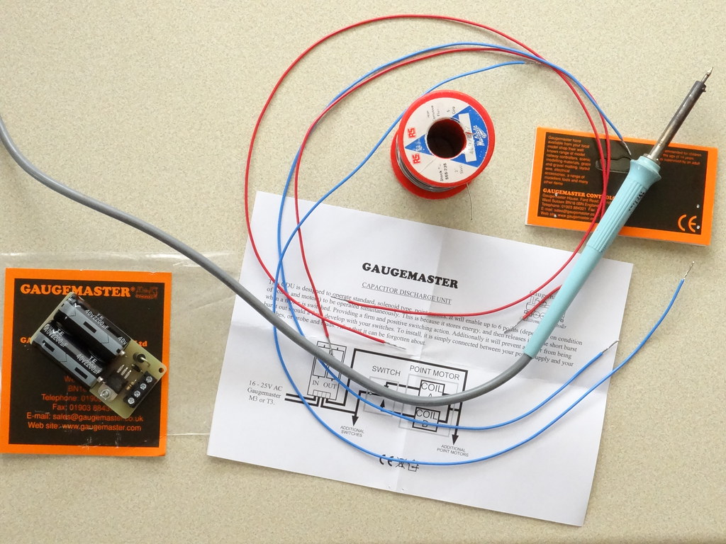
CDU with single 40v2200 µf capacitor
In the past I had purchased a small CDU on EBay. I inserted
it into the AC supply to my point motors. I was not impressed. Some points
would operate – most would not. As with a lot of things off eBay you need to do
some homework before bidding. Obviously I had not done enough research. I would
continue operating my points without CDU and would hope to resell the eBay
purchase at a later date.
Over the years I have built up a collection of over 100 Peco
points all fitted with Peco solenoids. During thirty years of operation I have
never had to replace a single Peco solenoid. Over the same period I have had to
replace maybe five or six momentary contact switches. Some of these were
damaged during the process of soldering the connections.
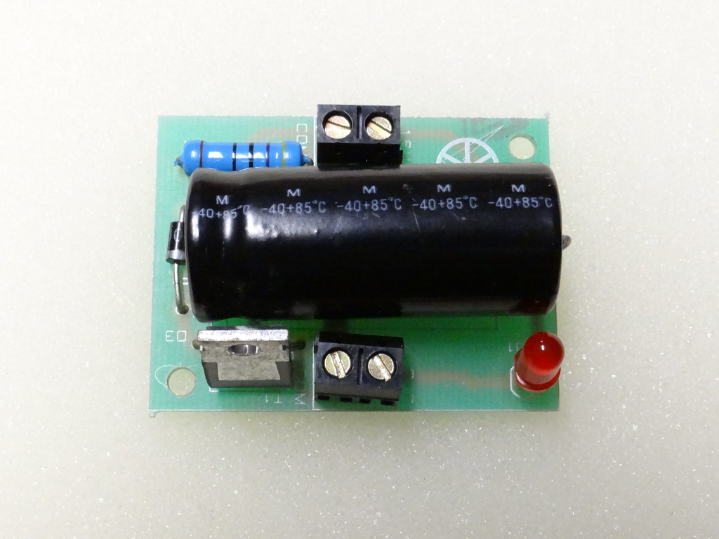
CDU with 2x 40v2200 µf capacitors
Following the suggestion here on RMweb that I was risking my
switches due to arcing I have now installed a couple of Gaugemaster CDUs (one
at the controller at each end of the layout). Initially the resulting operation
of my points was disappointing. Some worked brilliantly with a quick snapping
action. Others simply twitched and could not be persuaded to operate. Prior to
inserting the CDUs all points would operate. In order to persuade all my points
to continue operating with the CDU I had to replace a couple of I would say my
older momentary contact switches.
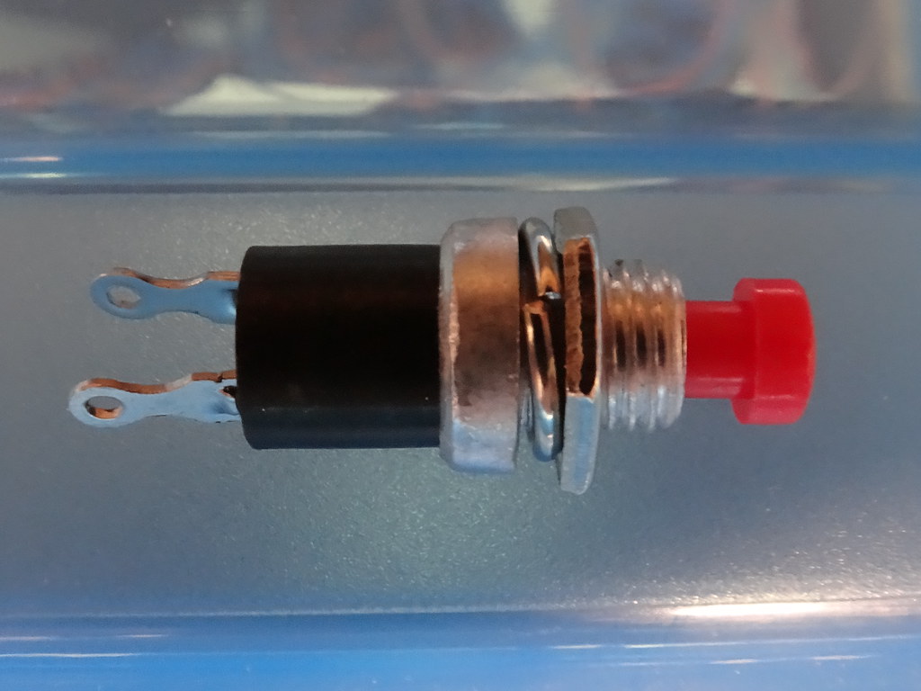
Mini round momentary push to make switch – UK sourced –
maximum current 1amp
The technical advice from Peco
for their PL10 point motor states as follows; “A Capacitor Discharge Unit can
be used but is not necessary.” If you go to the instructions for your Gaugemaster Controller (D, DS and P), then the
advice is to use a Capacitor Discharge Unit. So – some confusion?
A search of the Internet is equally unhelpful but does
provide some useful pointers. Firstly it is not all about electronics. I have
read that the internal friction within the solenoid motor can vary
significantly both due to manufacture and installation. (How many of us have
reattached a Peco point motor the other way round to get it to work?). Secondly
what about the resistance of the over-centre spring at the toe of the point?
Mass producing identical springs can be a problem and Peco provide a sliding
mechanism for the very purpose of adjusting this resistance. I have changed the
spring tension on numerous of my points to assist operation.
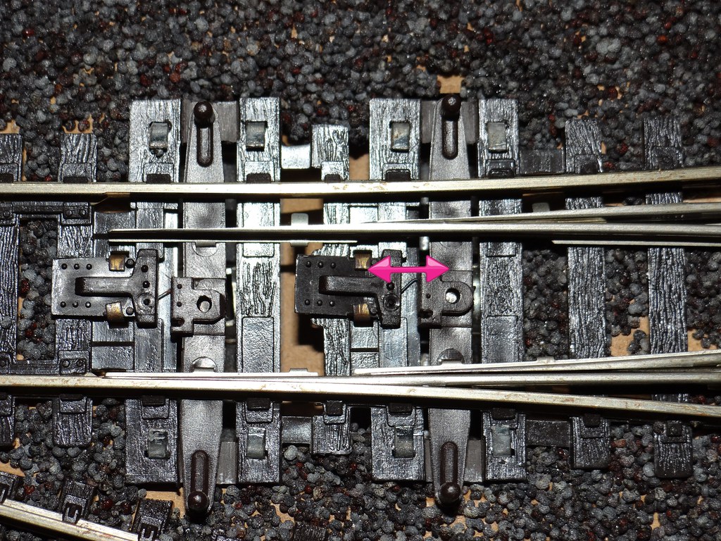
The slider for altering spring tension
Then as mentioned above there might the addition of a Peco
Accessory switch which will further add to the mechanical load.
My knowledge of things electrical is rather basic but there
seems to be a consensus on the Internet that the theoretical power needed to
operate one point solenoid motor is a little under 1 amp. Given the range of
mechanical resistance described above that might have to be overcome it could
be necessary to have anything up to 3 amps available to power each solenoid. If
there are 2 or more points to be operated simultaneously then the minimum
current requirement rises close to 2 amps. It follows that if the maximum
output from a controller or transformer is only 1amp (which seems to be fairly
typical) then there are going to be occasions when this will be insufficient to
operate a particular point, or set of points.
Rear of Gaugemaster Controller (Model P) showing
accessory sockets and rated power output
On the electrical side maintaining voltage at the point
motor is critical. Long distances between point motor and the controller or
transformer will add resistance to the circuit leading to a drop in voltage and
a corresponding lack of energy at the point motor. To minimise voltage drop I
use 16/0.2 wire (16 core each of 0.2mm2) for most of my connections.
Some people prefer an even larger cable and suggest 32/02.
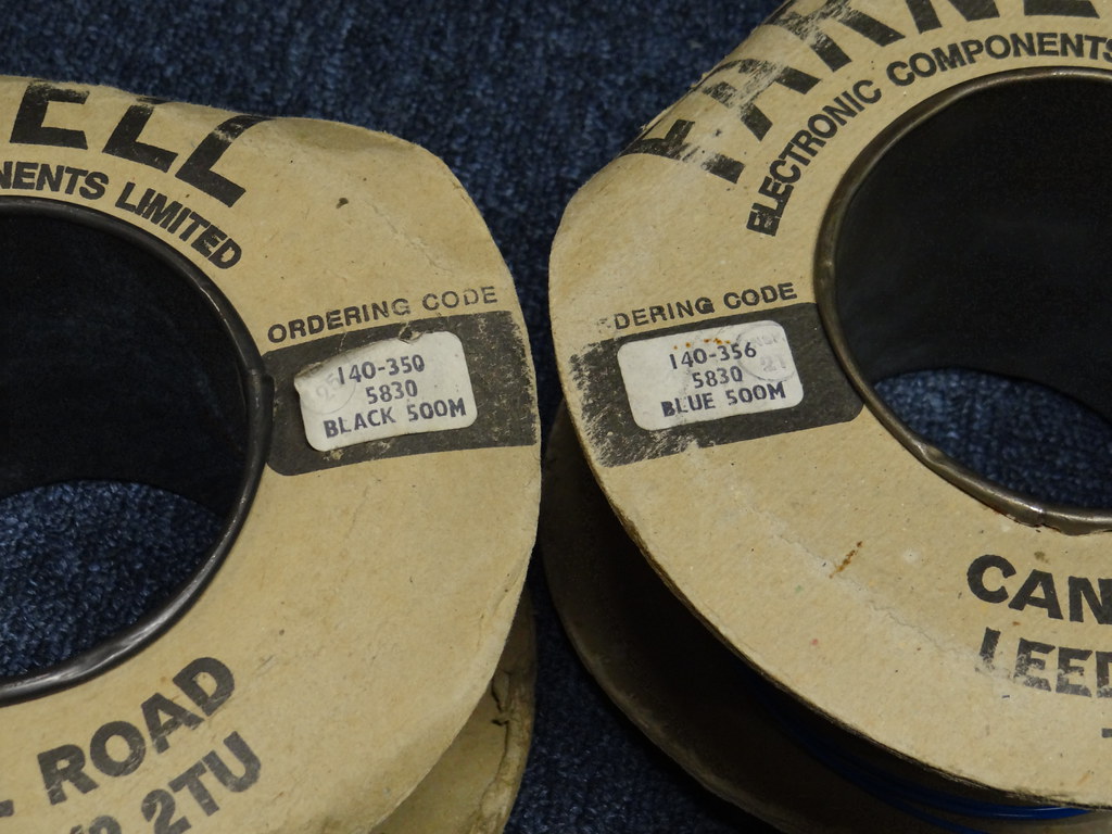
16/02 layout wire showing the old Farnell electronic
codes
Poor soldered joints or loose screwed connectors will add
additional resistance to the circuit causing further voltage drops preventing
solenoids from operating. I have also read on the Internet that the quality of
the power supply is a factor. It is not just the maximum current that is
important but the ability of the controller or transformer to continue to
supply the power under load, i.e whilst switching the point. I will say that I
use Gaugemaster units which appear to me to have a reasonable pedigree and are
able to maintain their rated output under most load conditions.
Finally and perhaps most importantly, what about the
switches? Where switches designed or rated for 0.5amp are used to switch supplies
of 3amp there will be arcing and erosion of the contacts. As the damage
increases so will the resistance across the circuit in turn accelerating the
damage and leading to total failure of the switch. Perhaps my cheap push button
switches with a maximum current rating of 1amp are not suitable for the job?
A trawl of the Internet showed apparently similar looking
switches on offer from different sellers with maximum current ratings as low as
0.5 and even 0.25amps. So – something else to think about. My switches were
bought over a period of time from different sources. I am not knowing their
original specification. The latest batch of switches sourced from a UK supplier
claim to have a life of 30000 operations (at 1amp). This life will decrease
dramatically with higher currents.
In summary, Peco point motors installed under ideal
mechanical conditions should work quite adequately using reasonable quality
push button switches without the need for a CDU. When the mechanical loading
increases due the use of auxiliary switches or there is a need to move two or
more points simultaneously, simple switching becomes more problematic.
Similarly if the voltage cannot be maintained due to the length of cable runs
or the quality of the power supply then there may not be sufficient power
available at the motor to operate the points.
It is at this point that the use of a CDU becomes relevant.
Capacitors within a CDU build up a store of power which is
delivered as a single instantaneous pulse to the solenoid. The increased energy
assists in overcoming mechanical losses in the point mechanism. Typically the
instantaneous voltage from the CDU will be double the input voltage from the
controller compensating for voltage losses in the wiring. The CDU is recharged
relatively slowly compared to the switching action meaning that there is less
demand on the power supply from the controller or transformer. Lastly the pulse
of energy is of short duration, reducing the damaging load on the switch and
preventing burn out of the contacts.
I have also read that the rapid ‘snap action’ induced by the
capacitor discharge unit can be detrimental to the construction of the point.
Time will tell as to whether installing my CDUs has been a good thing!


Comments