No.124 Dead Frogs and a 2P
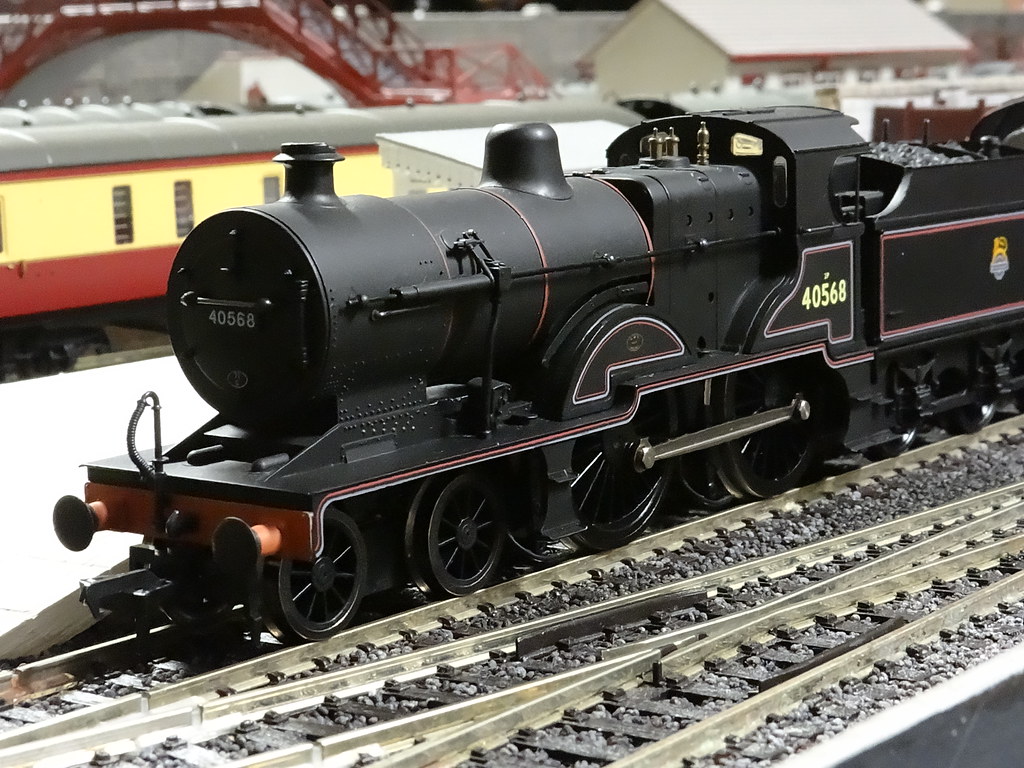
Back in July when I resurrected my Mainline ex LMS 2P 4-4-0 I must have been
very lucky because the video made at the time has the engine running perfectly smoothly. Since then attempts to
run at slow speed have resulted in the engine stalling on a diamond crossing
and worse still coming to an unexpected dead stop in out of the way non scenic
sections of the layout.
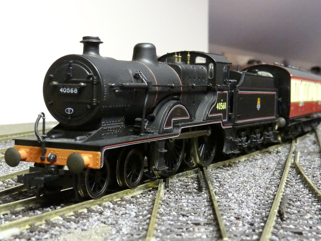
Peco Streamline Short Diamond and Mainline ex LMS 2P
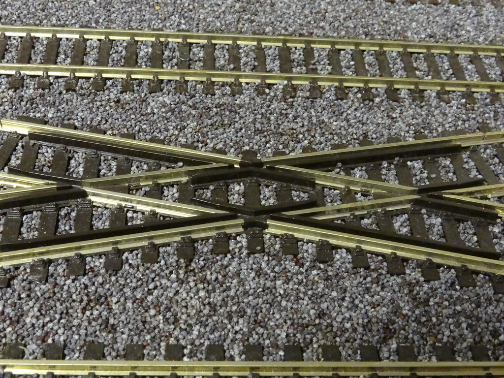
The diamond crossing provides the clue.
Peco Insulfrog Short Diamond
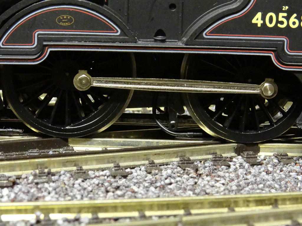
The Mainline 2P only has electrical pickups on its two pairs
of driving wheels. The tender drive unit is based on the old Airfix design with
all plastic wheels and rubber tyres. The spacing of the dead plastic frogs on
the Code 100 Peco small diamond crossing match perfectly with the wheel spacing
of the driving wheels on the 2P and it is not surprising that the engine stalls
on this piece of track.
Mainline ex LMS 2P
As to the other locations I am ashamed to say that close
examination of the track where the engine had unexpectedly stopped usually
showed a tiny build up of dirt on the rail head. The axles on the Mainline 2P
are not sprung and perhaps uneven track combined with dirt on the rail head was
sufficient to interrupt the electric current to the motor and bring the engine
to a dead stop.
I think I am correct in saying that the Peco Electrofrog
short crossing is only available with Code 75 rail. I could build my own
crossing in with Code 100 rail but that would not solve the problems caused by
dirty and uneven track. My favoured solution was to add electrical pickups to
the front bogie.
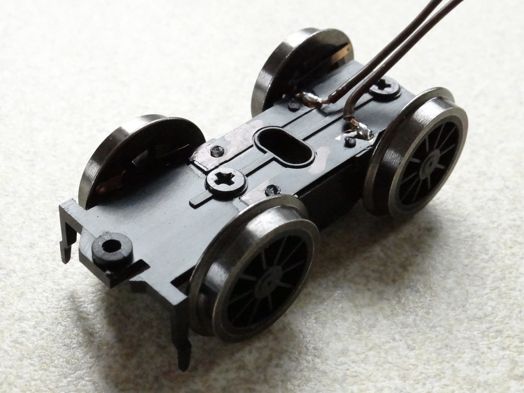
Hornby X6475 front bogie for Hornby R3028 Class 2P
As luck would have it Hornby have made available as spare
part X6475 the front bogie from their latest engine drive 2P (R3028). The bogie
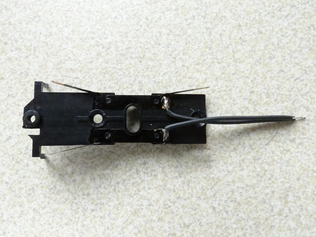
provided by Hornby requires wiring. My first attempts shown above used some
plastic coated wire stripped from a telephone cable. The bogie comes in two
parts and the view below shows the top with the wipers for the wheels removed
to aid soldering.
Second attempt using more flexible wire showing
wipers
The plastic coating turned out to be very rigid and
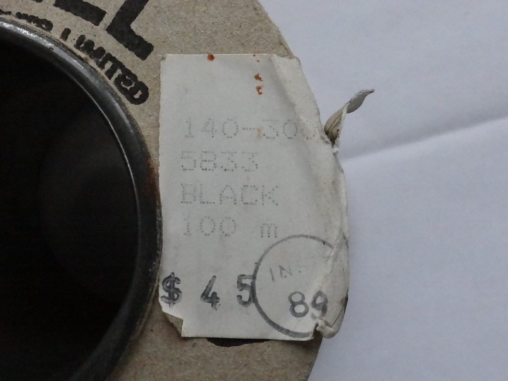
prevented free movement of the bogie. My second attempt utilised some rather
old instrument wire from Farnell in Leeds. The wire appeared to have a soft
natural rubber coating and was more flexible and to my liking.
Farnell Wire from the 80s or 90s
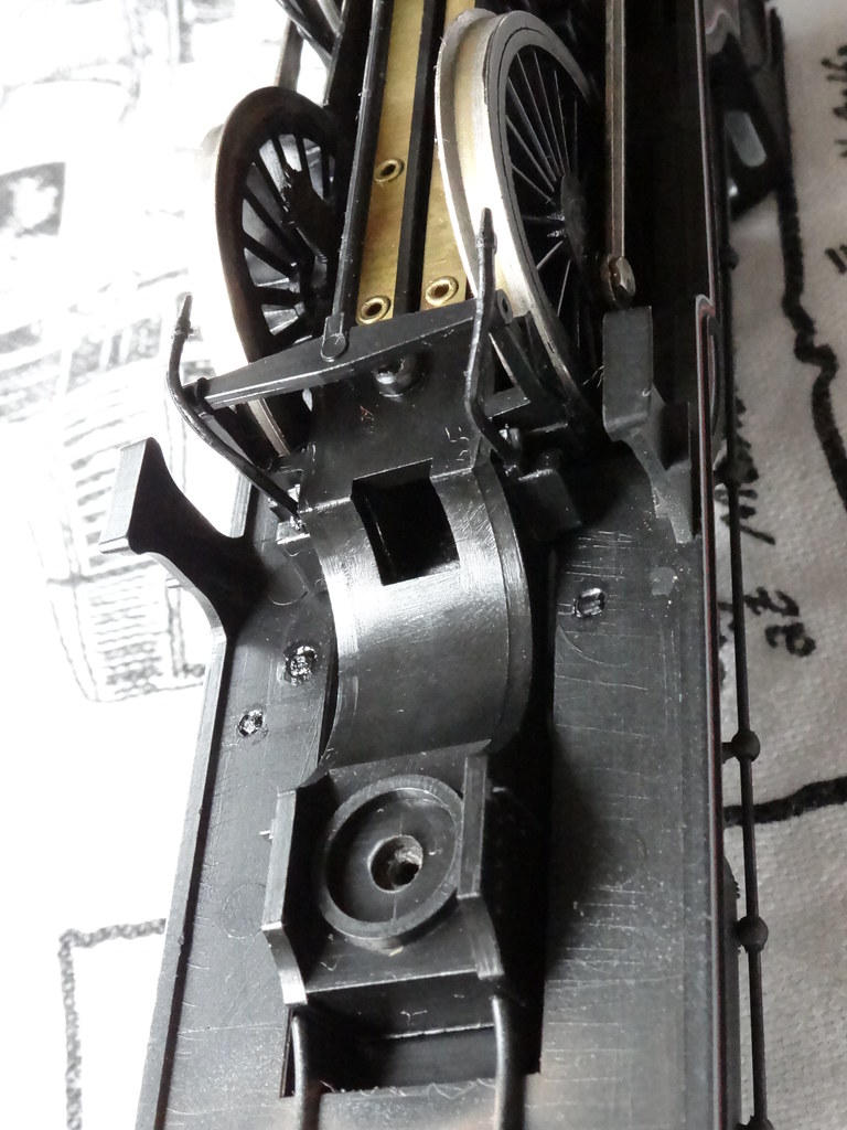
The design of the Mainline Chassis is interesting. It would
appear to incorporate a ready made passage for wiring from the front bogie to
the chassis bottom.
The underside of the Mainline chassis showing readymade
opening for wiring between the bogie and chassis bottom
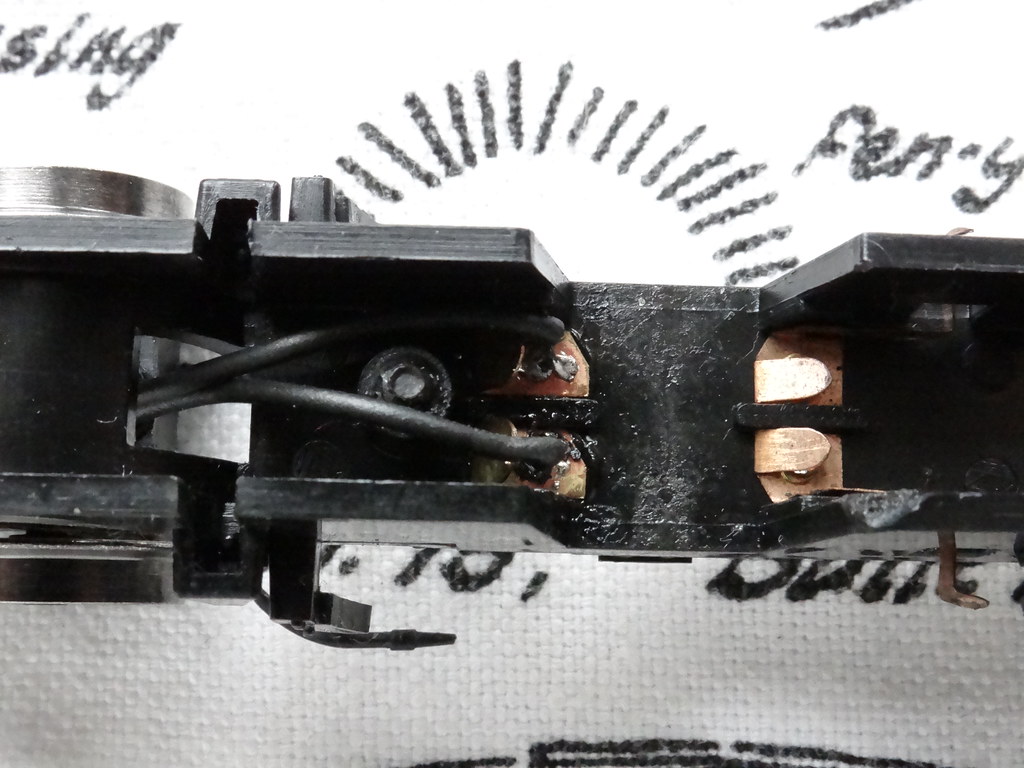
Also the arrangement for current collection from the driving
wheels inside the chassis bottom appears to have ready made tags for soldering
additional wires from the front bogie Did Palitoy design for bogie pickups and
were they omitted perhaps to save costs?
Inside Mainline Chassis Bottom showing solder tags for
wires from the bogie
For the record I used two 37mm lengths of wire for joining
the bogie to the contacts in the chassis bottom. This was the length before
stripping any of the insulation to make the soldered joints.
The finished product Mainline 2Pwith Hornby X6475
bogie
Certainly I think a very satisfying modification and well
worth the outlay on the Hornby spare part. For those of you with a couple of
minutes to spare there is video showing the modified 2P negotiating the
offending diamond crossing.
The layout uses cab control. All the pointwork was laid
‘straight out of the box, joined by Peco rail joiners. There was only one set
of track feeds to perhaps seven or eight feet of track.
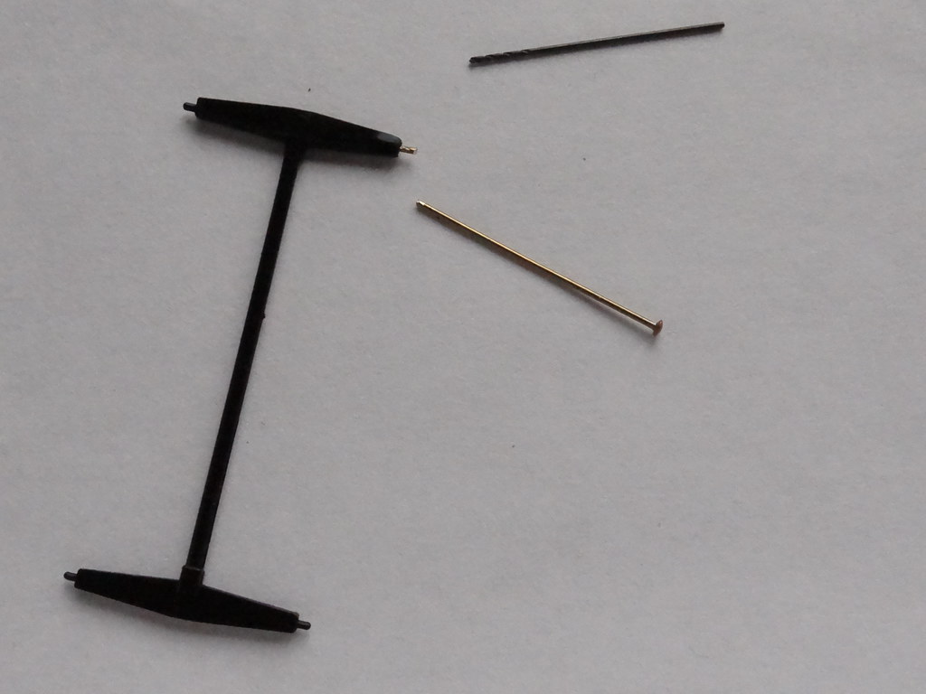
Brake rodding – repaired using 0.5mm drill and brass
dressmaking pin
I must be starting to lose my touch but I snapped off one of
the locating pins for the brake rodding. Not to worry it is easily repairable.
I used a 0.5mm drill bit rolled between the fingers to make a small hole in the
end of the plastic moulding where the broken pin had been. I then cut off a
short section from a brass dressmaker’s pin which I positioned in the newly
drilled hole before pushing it further into the plastic with a heated soldering
iron. I guess care is needed to avoid too much heat. On cooling the pin is held
rigidly in the plastic and the repair can be painted black to match the rest of
the plastic moulding.
Another good outcome.
Comments