No.131 Out of sight – perhaps, out of mind?
I was prompted by a recent question on RMweb to post a picture of the underside of my railway.
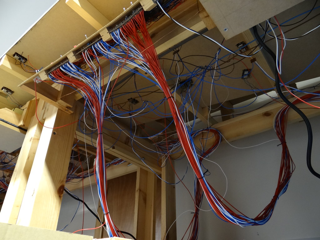 The underside of the control panel to what started off as the ‘Main Terminus’
I have tried to make an effort with my track laying and ballasting to create a good impression above board.
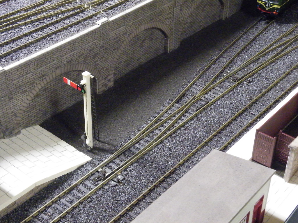 Platform detail at the ‘Main Junction’
However my aspirations for the view below ground never quite match up with the view above ground. A case of ‘All fur coat and no knickers’?
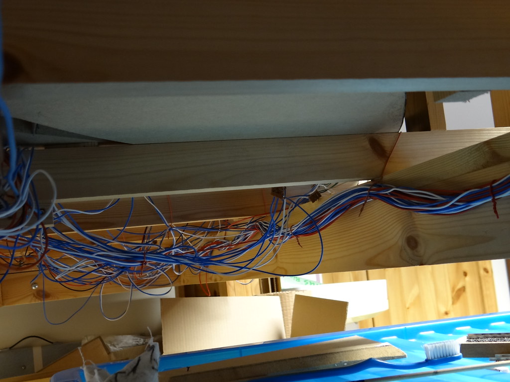 Underneath the arches – the view beneath the ‘Main Junction’
My layouts have always been DC controlled, that is where the track is powered with nominally 12 volt Direct Current. My early layouts used H & M controllers of the Duette and Clipper variety where speed control was obtained by varying the track voltage using a variable wire wound rheostat.
The present layout uses Gaugemaster Controllers where the DC current is pulsed at a constant voltage of around 14v DC. Speed control is achieved by varying the length of pulses. Because the voltage is always high there is good control at slow speeds – in contrast to the performance of variable rheostat controllers where the voltage drops off at low speed.
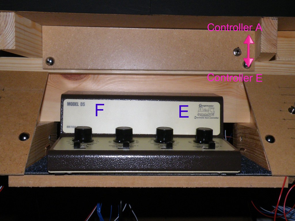 Gaugemaster DS Controller (Twin Track with Brake Simulator)
Electric power is applied to the track by short wires poked through small holes drilled beneath the rails. I prefer to use single core wire (1/0.6mm) colour coded red from the Control Panel and black for the Common Return. Wherever possible I have used resin multi core solder to attach the wires to nickel silver rail joiners. This way a lot of heat can be applied to the soldered joint without any concerns about melting adjacent plastic sleepers. Where there are no suitable rail joiners available the connecting wires may have to be soldered directly to the underside of the running rail. To minimise damage to the plastic sleepers I would cut through the webbing on both sides of the track to allow the sleeper units to be pulled wide apart whilst making the soldered connection.
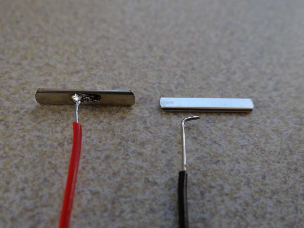 Connecting to the track - soldering 1/0.6mm wire to nickel silver rail joiners
For layouts of any size, or where there is more there are numerous engines present, it will be convenient to provide more than one controller and to divide the track up into ‘Sections’. This can be referred to as ‘Cab Control’ and is illustrated here in a diagram taken from the Reverend Beale’s 1950s book ‘West Midland’.
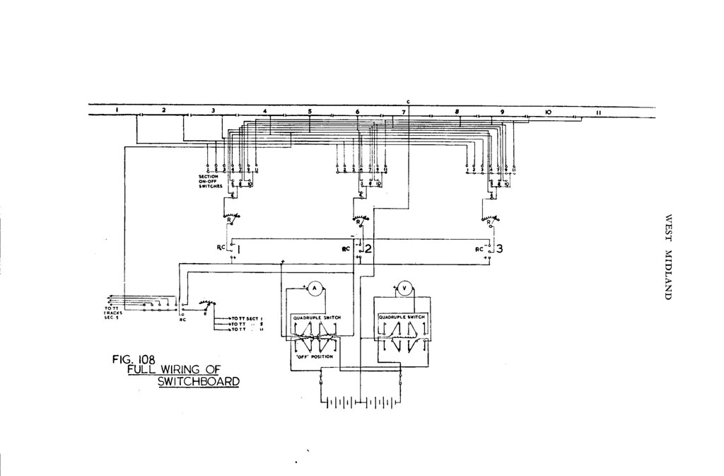 Cab Control with three controllers and eleven sections
Edward Beale used battery power and a ‘split potential’ system to obtain forward and reverse. With today’s modern mains powered controllers the layout wiring is much simplified. Where each controller is fed from a totally separate power supply or separate windings on a multi wound transformer such as used in the Gaugemaster D/DS/Q range, one wire from the controlled output can be taken to the Common Return and the other wire from the controlled output taken to the Section Switches. Edward Beale used simple on/off Section Switches (Single Pole / Single Throw or SPST). In his drawing there was nothing to stop individual sections being powered by two or even three of his controllers all at the same time. I prefer a more orderly (and safer) approach. By grouping Sections together on one Control Panel and restricting the number of Controllers powering the Panel to two it is simpler and safer to power the individual Sections using Single Pole / Double Throw Centre Off switches (SPDT). This way power to individual Sections can only be applied from one controller at a time and the ‘centre off’ position allows the Section to be thrown completely dead allowing safe storage of a complete train.
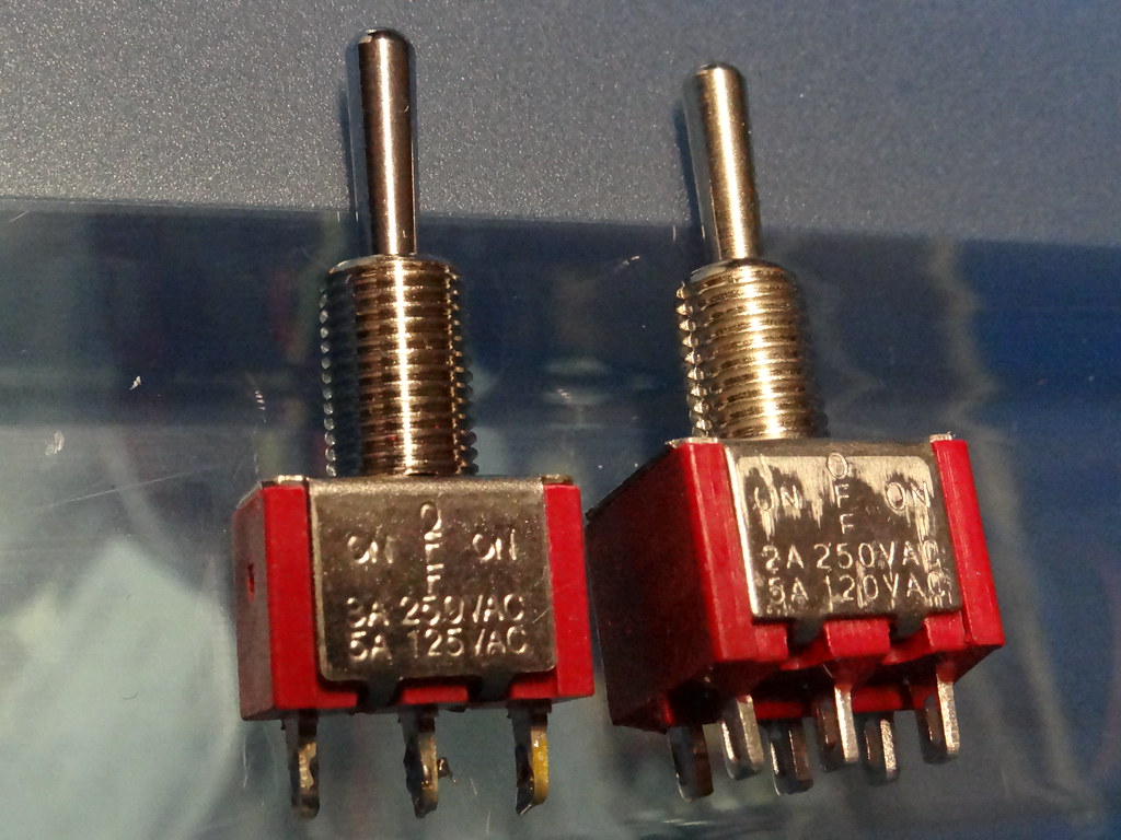 Centre Off Switches - SPDT left DPDT right
The Section Switches can be arranged on a Control Panel, in my case based on a diagrammatic track plan.
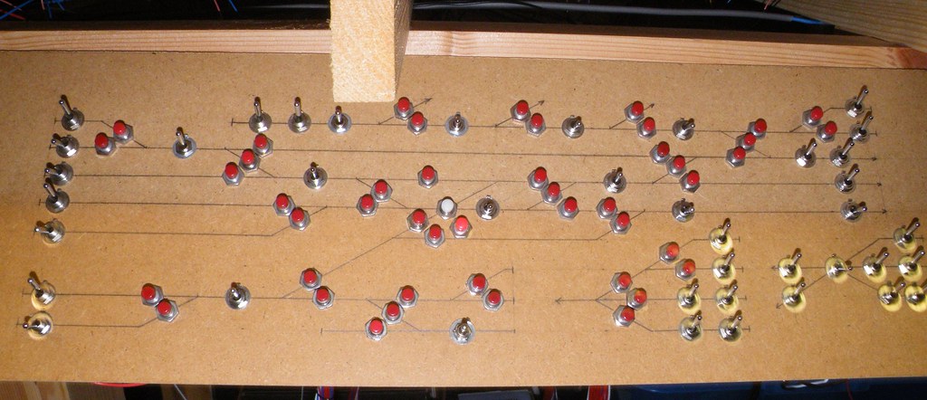 Panel Front – The Main Terminus that was
I use heavy duty copper wire (stripped from 240v mains cable) to distribute the power (blue for controller A and brown for controller B ) around the control panel. Connections between the switches and the heavy duty copper are made with single core 1/0.6mm wire. Single core wire has the advantage that it can be bent and will hold its shape. The same size wire is also used to connect the output from the switches to strips of Vero type printed circuit board which I use as an interface between the Control Panel and the layout.
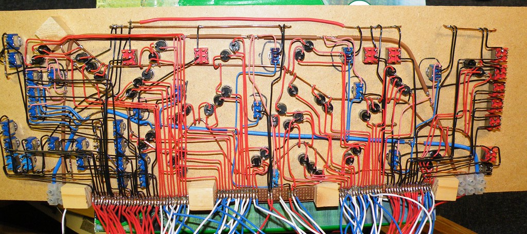 Panel Rear – The Main Terminus that was
The Control Panels also include ‘Momentary Contact’ push button switches for point control – the red wires. These are powered by their own heavy duty copper supply connected to the 16volt AC auxiliary output on the Controller via a Capacitor Discharge Unit (CDU).
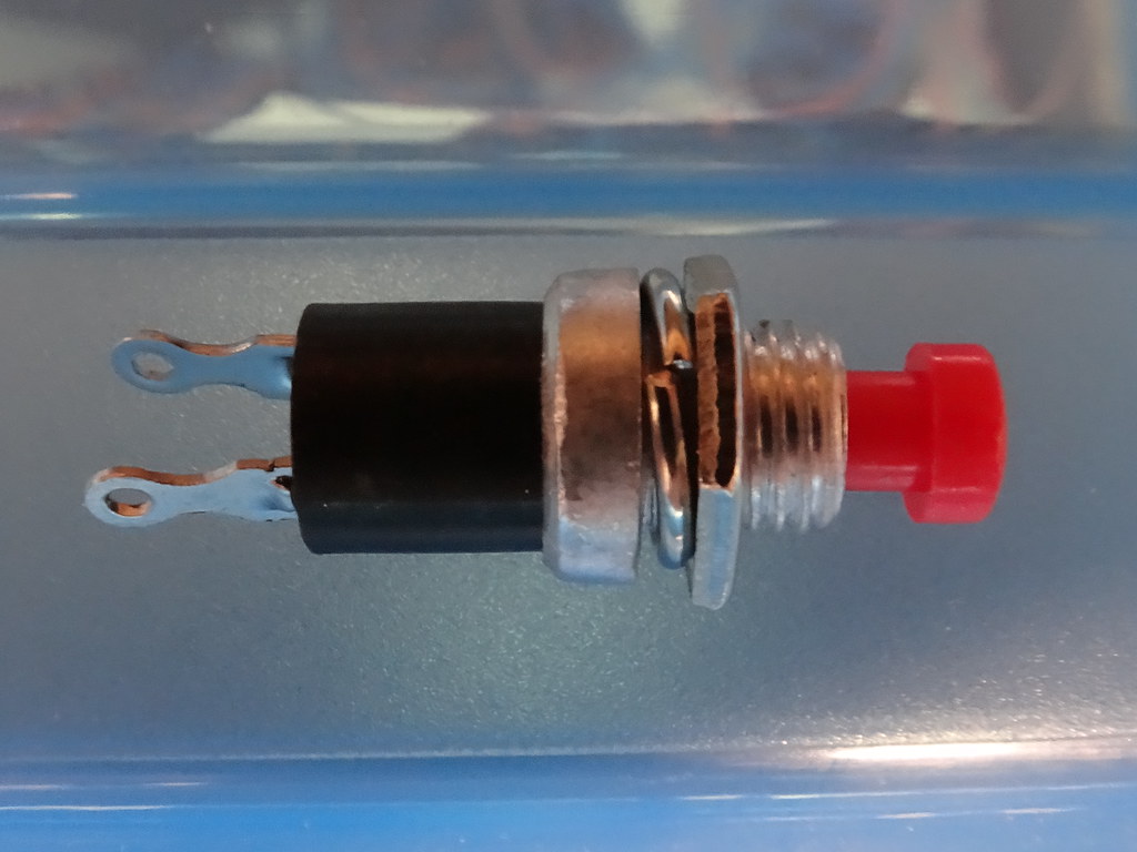 Momentary Contact Push Button Switch
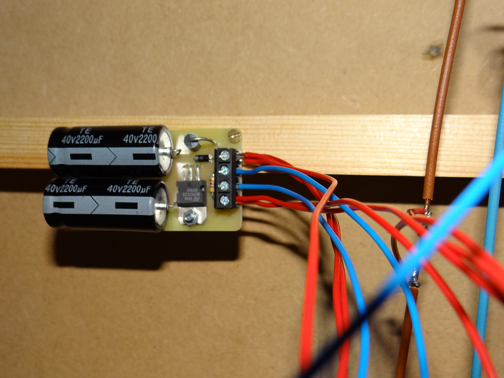
Gaugemaster CDU Installation
The output from the Control Panel is then distributed around the layout using 16/0.2mm multi strand wire.
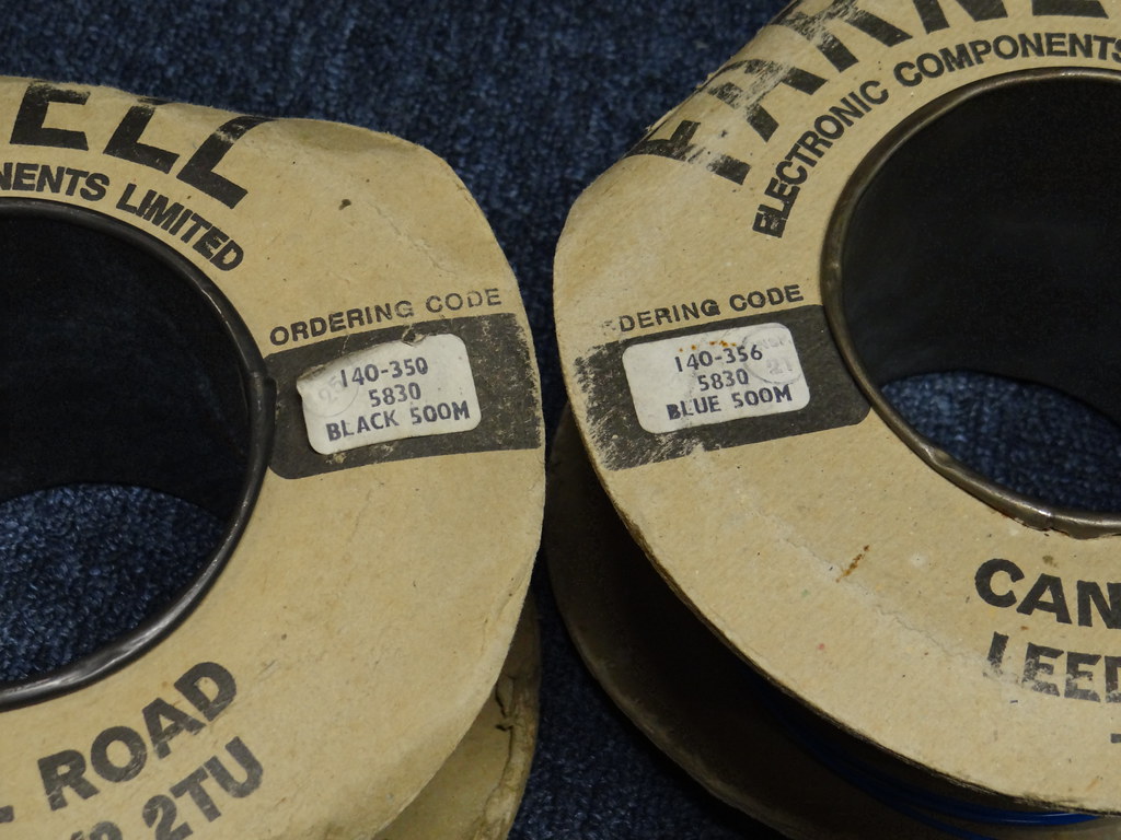 Multi strand wire - 140-350 / 140-356 are old Farnell codes for 16/0.2mm gauge wires
 The underside of the control panel to what started off as the ‘Branch Terminus’
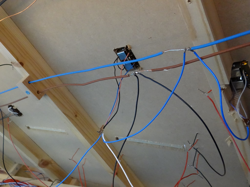
My system of colour coding had to be seriously modified to take account of the limited stock of cable that I had available. I had reels of blue, white, black and red. As a result I used ‘red’ to distribute power from the Section Switches to the track and ‘black’ to connect the return side of the track to the brown Common Return running beneath the baseboards. The power for the point motors was carried by ‘blue’ and ‘white’ cables which connect the push buttons to the two opposing sides of the solenoid motors. Just to confuse matters I also used ‘blue’ to connect the return side of the solenoids to the ‘blue’ Common Return for the points. It is very important to note that the so called Common Return for the points can ONLY be powered from the auxiliary output of ONE controller. In my case the auxiliary power supply from one controller operates all the points at one end of the layout (over a twenty foot radius) via one CDU.
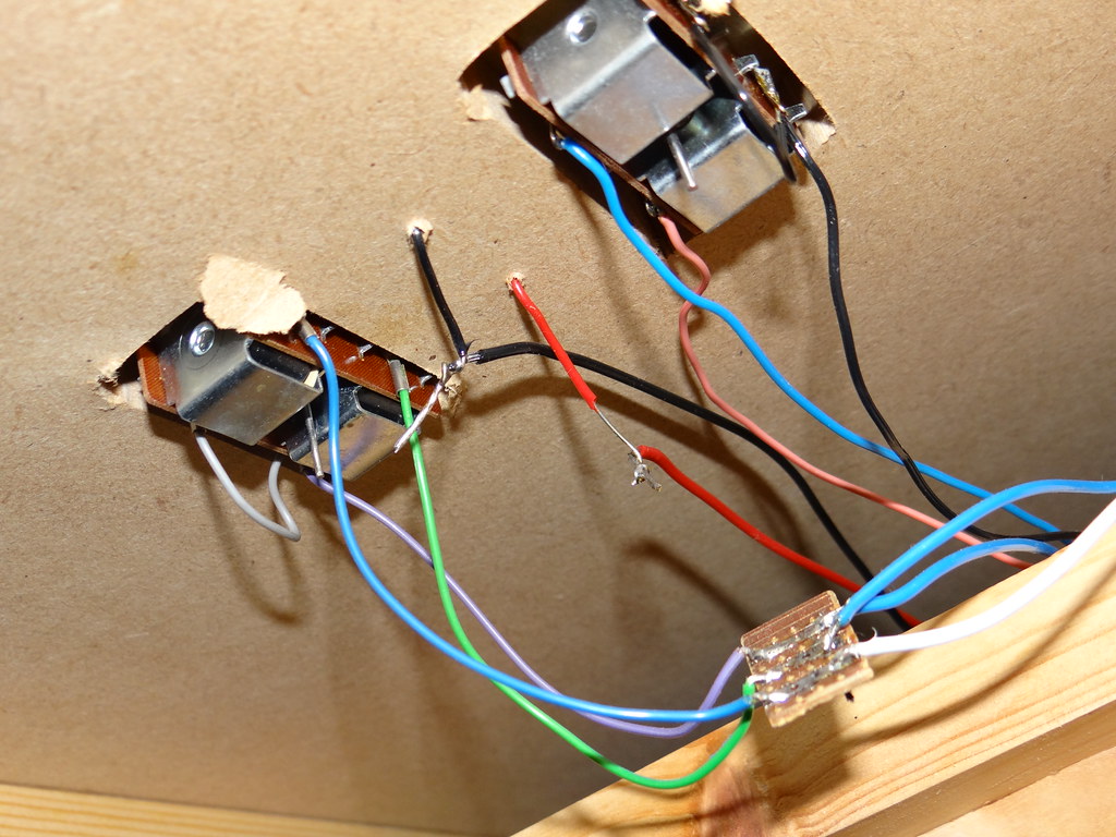
Close up showing under board connections to track (red and black) and to point motors (blue and white)
The final connections of the 16/0.2mm multi wires to the 1/0.6mm single core from the rail joiners was achieved by tinning both wires, wrapping the single core wire around the larger multi strand wire and then applying the hot iron to fuse the soldered wires together. For the connections to the point motors I used off cuts of the Vero type printed circuit board. The 16/0.2mm wire can be a tight fit in the holes in the Vero board and I find it makes life much easier to run a 1/16 inch drill through the holes before attempting to fit the multi strand wire.
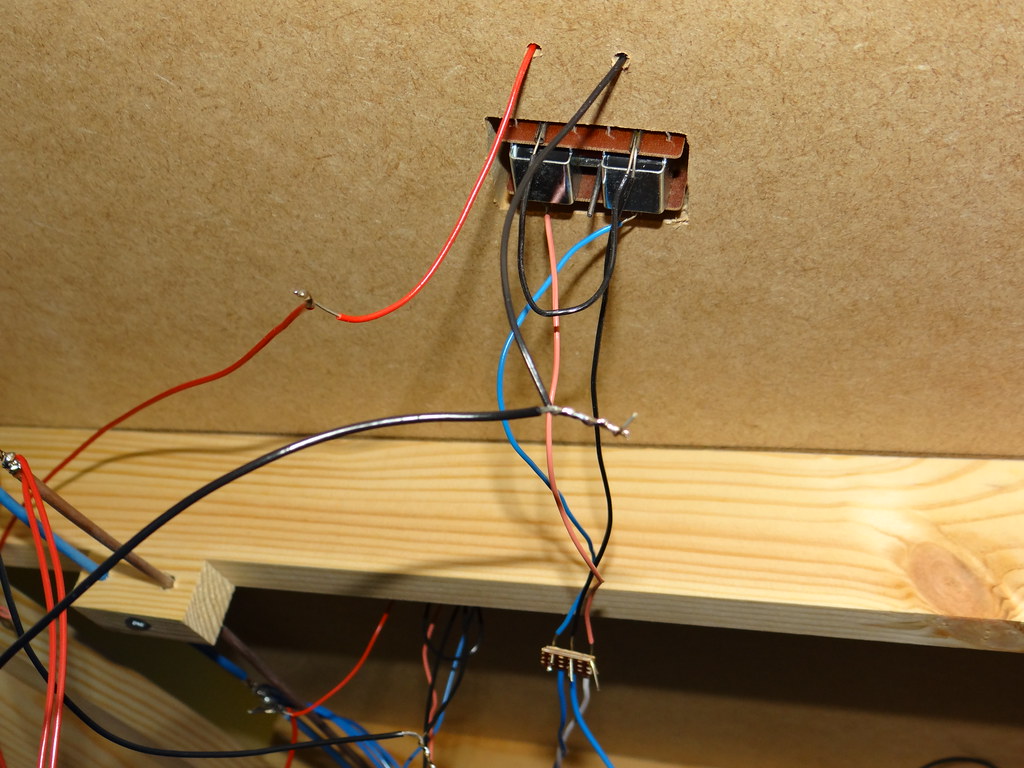 Another close up of the under board power and point connections – NB the ‘Blue’ and ‘Brown’ Common return wires on the left
Being a static layout I am happy to leave my soldered connections ‘bare’ and I rely on separation (by air) to provide the necessary insulation between the different wires. This approach might not suit everyone.
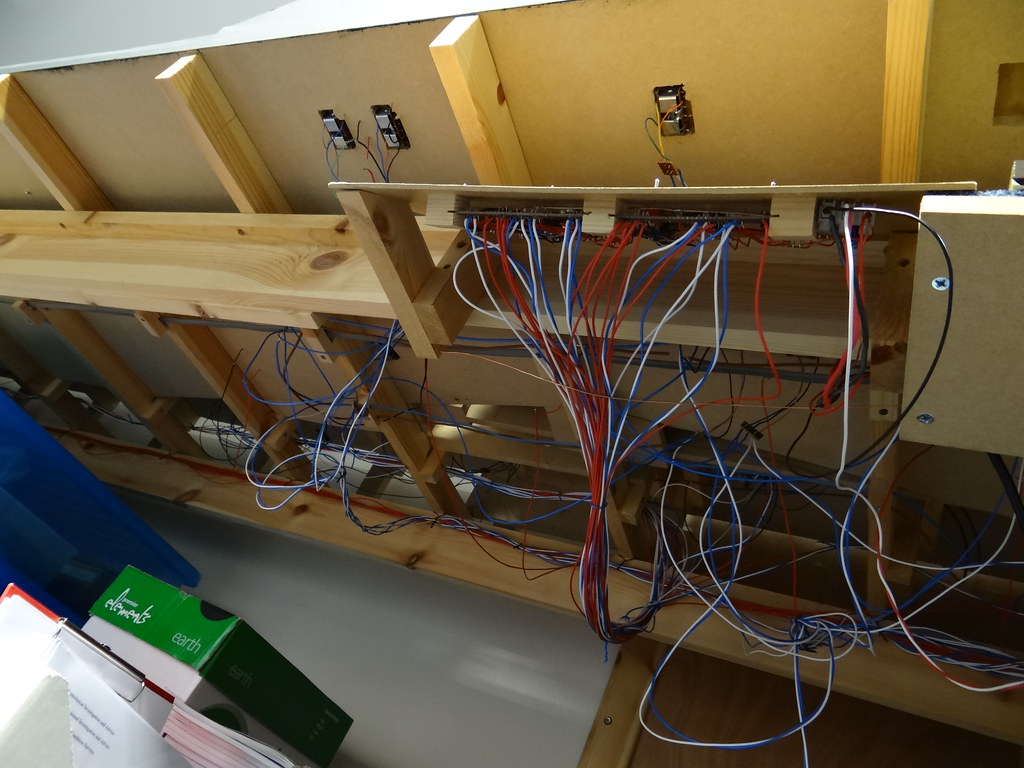
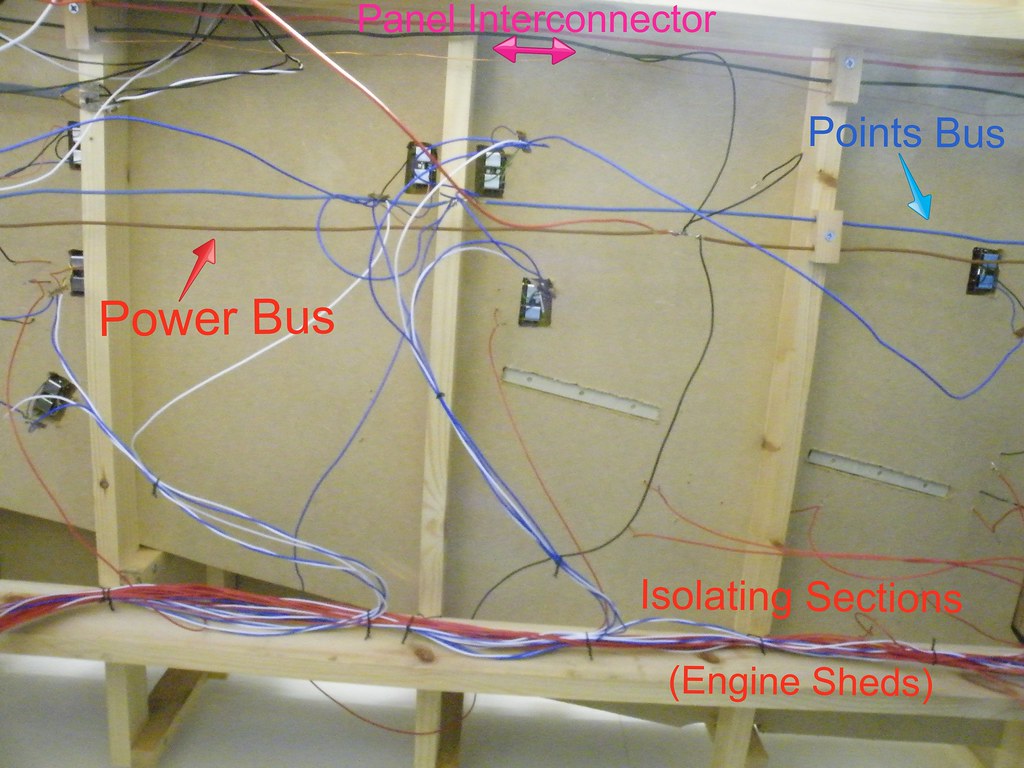
 A general view of the layout wiring highlighting the connections to the Common Return wires (stripped from mains cable)
Being a static layout also means that I am not able to turn the layout over and work from above. This is my excuse for leaving a lot of the wire with plenty of ‘spare length’ to work with. To try and introduce some order I do bundle the individual wires together to form cables using short pieces of 1/0.6mm wire. I also use short lengths of 1/0.6mm wrapped around baseboard framing to form hangers for the bundled cables. I use wood offcuts as clamps to hold the heavier Common Return wires in place.
 Beneath the Board
I do wonder if these images of bundles of wires are an advertisement to change to ‘Digital’. In response I would say that the concept of individual wires from separate switches is simple to understand and enables faults to be easily traced and fixed.
The underside of the control panel to what started off as the ‘Main Terminus’I have tried to make an effort with my track laying and ballasting to create a good impression above board.
However my aspirations for the view below ground never quite match up with the view above ground. A case of ‘All fur coat and no knickers’?
My layouts have always been DC controlled, that is where the track is powered with nominally 12 volt Direct Current. My early layouts used H & M controllers of the Duette and Clipper variety where speed control was obtained by varying the track voltage using a variable wire wound rheostat.
The present layout uses Gaugemaster Controllers where the DC current is pulsed at a constant voltage of around 14v DC. Speed control is achieved by varying the length of pulses. Because the voltage is always high there is good control at slow speeds – in contrast to the performance of variable rheostat controllers where the voltage drops off at low speed.
Electric power is applied to the track by short wires poked through small holes drilled beneath the rails. I prefer to use single core wire (1/0.6mm) colour coded red from the Control Panel and black for the Common Return. Wherever possible I have used resin multi core solder to attach the wires to nickel silver rail joiners. This way a lot of heat can be applied to the soldered joint without any concerns about melting adjacent plastic sleepers. Where there are no suitable rail joiners available the connecting wires may have to be soldered directly to the underside of the running rail. To minimise damage to the plastic sleepers I would cut through the webbing on both sides of the track to allow the sleeper units to be pulled wide apart whilst making the soldered connection.
For layouts of any size, or where there is more there are numerous engines present, it will be convenient to provide more than one controller and to divide the track up into ‘Sections’. This can be referred to as ‘Cab Control’ and is illustrated here in a diagram taken from the Reverend Beale’s 1950s book ‘West Midland’.
Edward Beale used battery power and a ‘split potential’ system to obtain forward and reverse. With today’s modern mains powered controllers the layout wiring is much simplified. Where each controller is fed from a totally separate power supply or separate windings on a multi wound transformer such as used in the Gaugemaster D/DS/Q range, one wire from the controlled output can be taken to the Common Return and the other wire from the controlled output taken to the Section Switches. Edward Beale used simple on/off Section Switches (Single Pole / Single Throw or SPST). In his drawing there was nothing to stop individual sections being powered by two or even three of his controllers all at the same time. I prefer a more orderly (and safer) approach. By grouping Sections together on one Control Panel and restricting the number of Controllers powering the Panel to two it is simpler and safer to power the individual Sections using Single Pole / Double Throw Centre Off switches (SPDT). This way power to individual Sections can only be applied from one controller at a time and the ‘centre off’ position allows the Section to be thrown completely dead allowing safe storage of a complete train.
The Section Switches can be arranged on a Control Panel, in my case based on a diagrammatic track plan.
I use heavy duty copper wire (stripped from 240v mains cable) to distribute the power (blue for controller A and brown for controller B ) around the control panel. Connections between the switches and the heavy duty copper are made with single core 1/0.6mm wire. Single core wire has the advantage that it can be bent and will hold its shape. The same size wire is also used to connect the output from the switches to strips of Vero type printed circuit board which I use as an interface between the Control Panel and the layout.
The Control Panels also include ‘Momentary Contact’ push button switches for point control – the red wires. These are powered by their own heavy duty copper supply connected to the 16volt AC auxiliary output on the Controller via a Capacitor Discharge Unit (CDU).
Gaugemaster CDU Installation
The output from the Control Panel is then distributed around the layout using 16/0.2mm multi strand wire.
My system of colour coding had to be seriously modified to take account of the limited stock of cable that I had available. I had reels of blue, white, black and red. As a result I used ‘red’ to distribute power from the Section Switches to the track and ‘black’ to connect the return side of the track to the brown Common Return running beneath the baseboards. The power for the point motors was carried by ‘blue’ and ‘white’ cables which connect the push buttons to the two opposing sides of the solenoid motors. Just to confuse matters I also used ‘blue’ to connect the return side of the solenoids to the ‘blue’ Common Return for the points. It is very important to note that the so called Common Return for the points can ONLY be powered from the auxiliary output of ONE controller. In my case the auxiliary power supply from one controller operates all the points at one end of the layout (over a twenty foot radius) via one CDU.
Close up showing under board connections to track (red and black) and to point motors (blue and white)
The final connections of the 16/0.2mm multi wires to the 1/0.6mm single core from the rail joiners was achieved by tinning both wires, wrapping the single core wire around the larger multi strand wire and then applying the hot iron to fuse the soldered wires together. For the connections to the point motors I used off cuts of the Vero type printed circuit board. The 16/0.2mm wire can be a tight fit in the holes in the Vero board and I find it makes life much easier to run a 1/16 inch drill through the holes before attempting to fit the multi strand wire.
Being a static layout I am happy to leave my soldered connections ‘bare’ and I rely on separation (by air) to provide the necessary insulation between the different wires. This approach might not suit everyone.
Being a static layout also means that I am not able to turn the layout over and work from above. This is my excuse for leaving a lot of the wire with plenty of ‘spare length’ to work with. To try and introduce some order I do bundle the individual wires together to form cables using short pieces of 1/0.6mm wire. I also use short lengths of 1/0.6mm wrapped around baseboard framing to form hangers for the bundled cables. I use wood offcuts as clamps to hold the heavier Common Return wires in place.
I do wonder if these images of bundles of wires are an advertisement to change to ‘Digital’. In response I would say that the concept of individual wires from separate switches is simple to understand and enables faults to be easily traced and fixed.


Comments