No.138 Kingly matters.
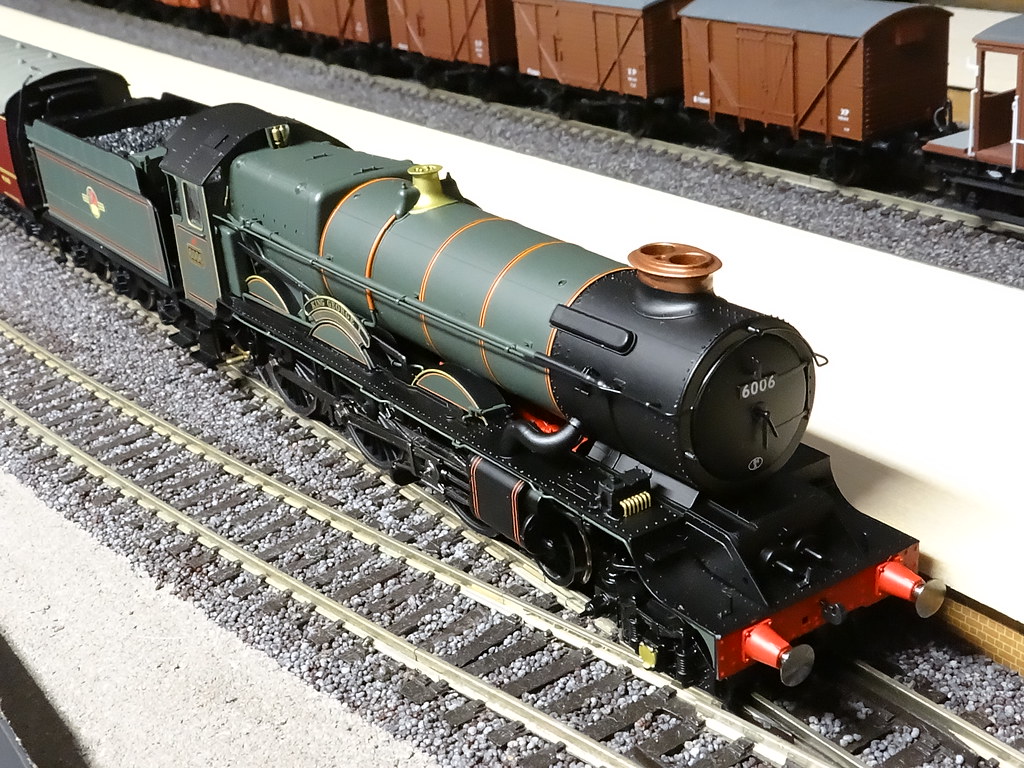
Hornby have released a second batch of their ex GWR King Class locomotives. With retailers selling these new models at a lower price than the price I paid this time last year for King Edward VIII, I have succumbed and invested in a model of 6006 George II.
Hornby R3384 6006 King George II
The Hornby Kings are rather splendid models. However I do
wish Hornby would sort out their vacuum packaging.
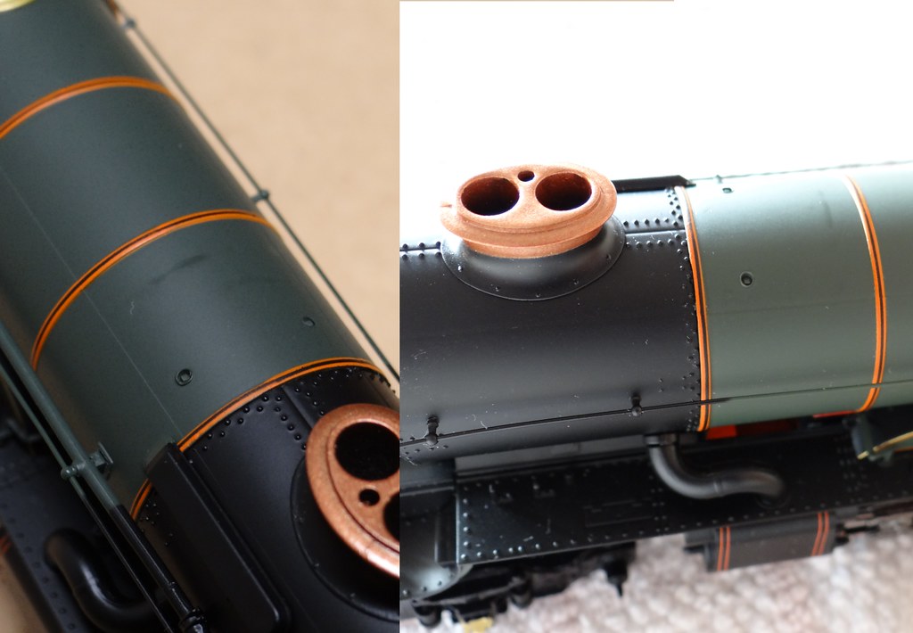
Rub marks from packaging, Hornby Kings William and
George
I had three Kings through my hands this Christmas and all
showed rub marks on top of the boiler behind the chimney. One was ‘a William’
whilst two were ‘Georges’. They were sourced from two retailers, one of whom
confided that the rub marks were a known problem and that all his stock was similarly
marked, some more than others. Might this account for the lower prices?
I would keep one model. It seemed to run nicely. The tender
body did not sit flush on its chassis. I thought at first that this was simply
the handrails had not been fitted into their preformed holes. No, that was not
the problem. I needed to file the rough edge off the little PCB that carries
the plug socket so that it would fit snugly into its recess and allow the
tender top to be screwed down level. Whilst ‘playing’ with the tender body the
two handles (brake or water scoop?) fell off and had to be reattached. I would
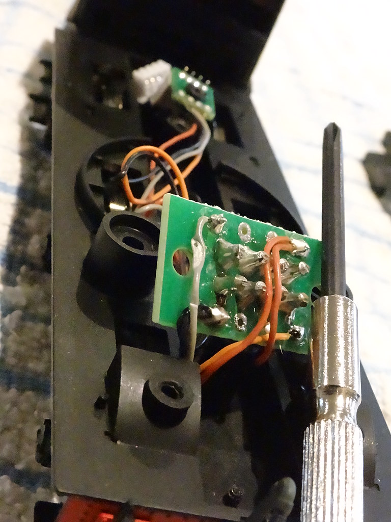
say not much sign of any adhesive. The main PCB (the one that carries the DC
chip or blanking plate) also caught my eye. It seemed to be sitting at a jaunty
angle.
The large PCB (for the DC chip) in the foreground and the
small PCB with the plug socket in the background
Unscrewing the PCB revealed that it had been fastened down
on top of one of the connecting wires. I don’t know whether the wire had been
compromised but I cut it back and resoldered it.
Back in business I would give the engine a longer run
around. I would try it on the rake of seven coaches that I used with King
Edward VII. Out of its box King Edward could manage seven coaches up and around
my layout, almost as well as one of Hornby’s Britannias. However King George
just slipped to a halt. Now, there was a puzzle, both Kings weighed the same!
On closer inspection I realised that King George was not sitting rock steady on
the track. On one side the centre driving wheel seemed to be acting as a pivot
preventing either the rear driving wheels or the front driving wheels from
resting on the track.
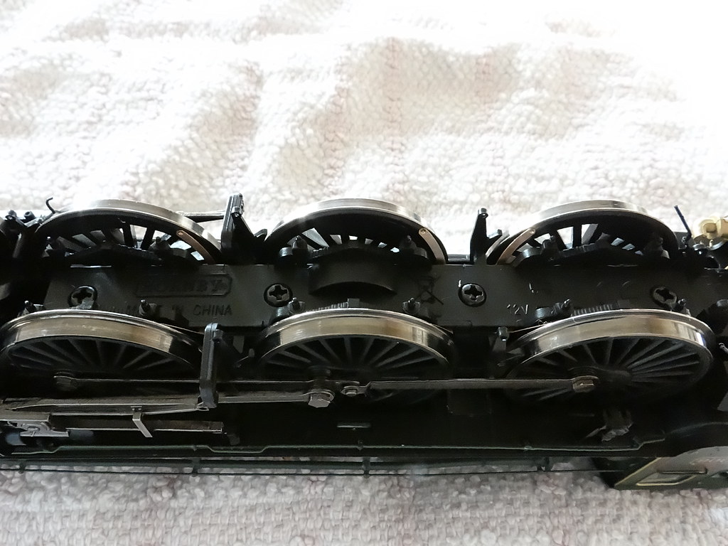
Keeper plate, Hornby King George II
The bottom plate or keeper plate is held in place with four
screws. The screws can be slackened off and the plate and screws lifted out
together.
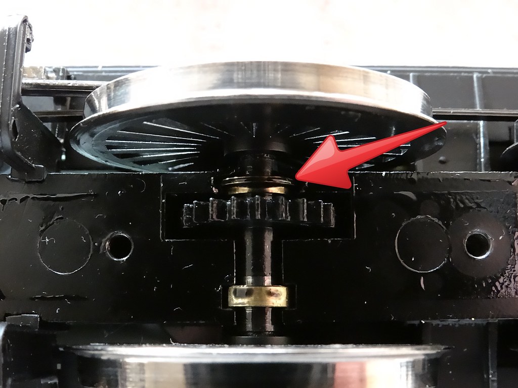
Centre Driving Wheels, Hornby King George II
The axle for the centre driving wheels runs in two brass
bearings which sit in slots in the Mazac chassis casting. In my case the large
diameter narrow bearing (highlighted with the red arrow) needed to be pushed
further into the chassis.
Some useful tools, a Philips screw driver for releasing
the keeper plate, a tiny flat screw driver to enlarge the bearing slot and a wrench for the undoing the crank pins.
I used a small adjustable wrench to undo the crank pins to
the centre drivers, which can then be lifted clear without disturbing the
coupling rods, or the front and rear drivers.
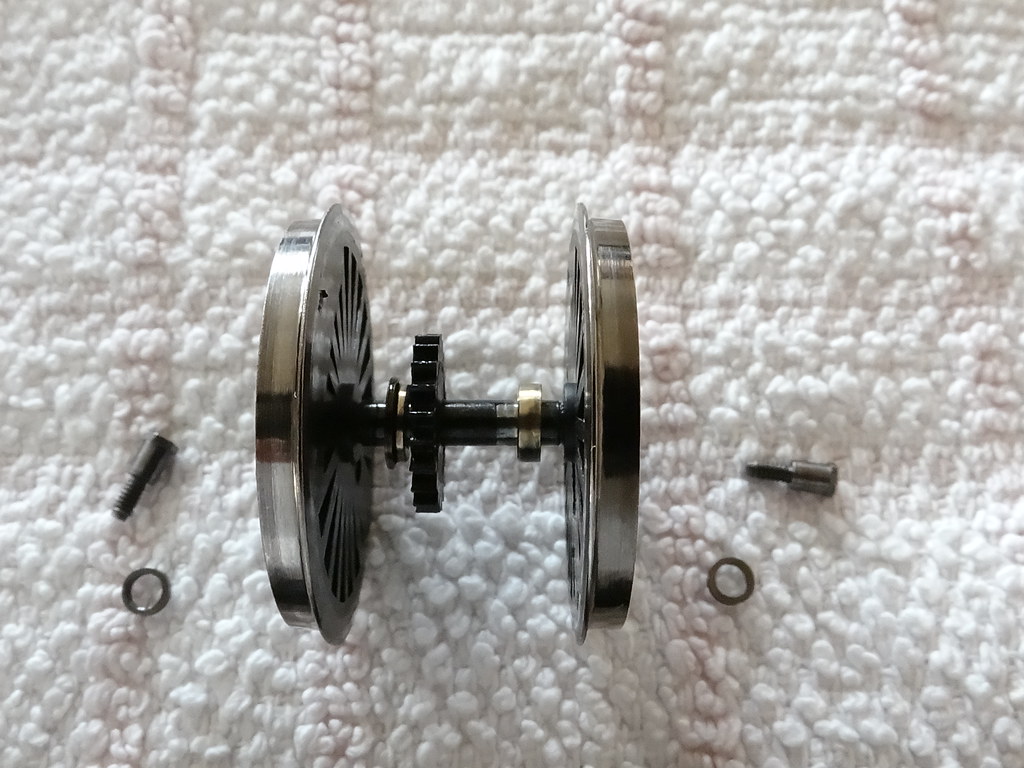
Centre drivers
The wheels, pins and spacers need to be put safely to one
side. (The spacers on the King are particularly thin
and when I Iost one last time round I had to devise a way of making the
thinner spacer from the more readily available but larger sized Hornby spares.)
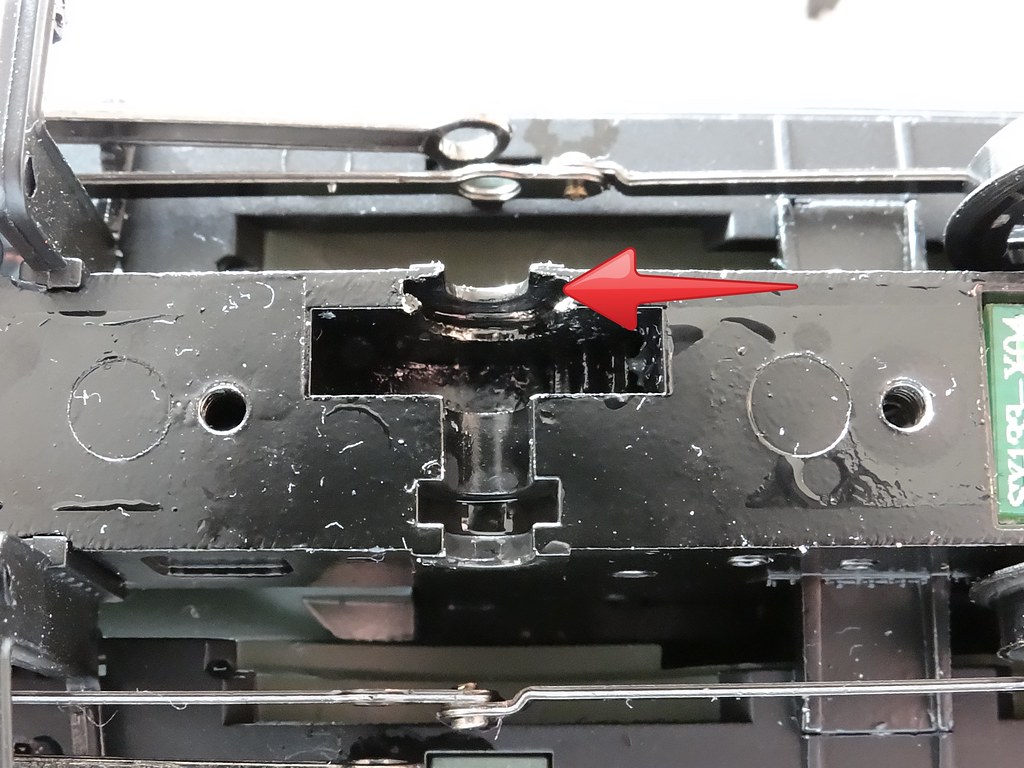
The ‘slot’
With the centre wheel set removed the bearing slot
highlighted with the red arrow can be gently scraped deeper with a tiny flat
screwdriver. I hate misusing tools but the Mazac is very soft and ‘needs must’.
I didn’t want to make the slot over deep so I kept replacing the wheel set to
check on progress.
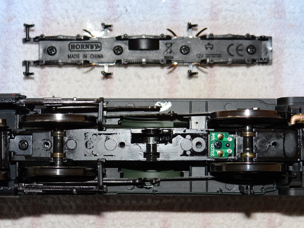
Finished
I have added another view above prior to reassembly. Note
the spring contacts for transferring electric power from the wheel wipers on
the bottom plate.
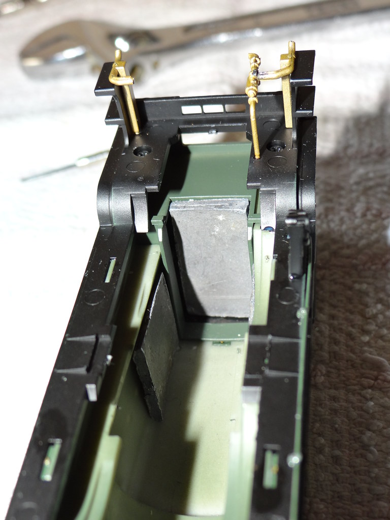
Some extra lead weights
For whatever reason George (not Gordon) was still reluctant
to manage Edward’s seven coaches up my gradients. This was solved by adding
some pieces of 2mm (1/8 inch) sheet lead attached by double sided tape to the
sides and rear of the firebox as shown in the view above.
Now then, what about some sound on DC?

Comments