No. 169 GWR - the Great Way Round – the construction.
Recapping from my last Post, some fifteen years ago when the layout was conceived there was a Mainline Terminus and a high level Branch Terminus, both constructed up against the plasterboard enclosure housing the Aga flue. It was not long before the Mainline Terminus was converted to a through station with the running lines skirting the outside of the plasterboard enclosure. This provided for a dumbbell shaped layout with reversing loops and storage sidings at both ends. Most importantly it allowed continuous running. I do like to watch trains running. How could the single track branch line be made into a continuous run?
Life moves on, the Aga is now electric and the flu no longer carries hot gases. I mused about a tunnel through the plaster board enclosure with a new connection back down to the through station (the Mainline Terminus that was).

The Plaster Board Box
The catalyst for this work was the appearance of some off cuts of ¾ inch plywood. By stint of good fortune these were a perfect height and width to form a box for a tunnel. All that was necessary was to glue and screw the bits together to form a solid box (almost square) which was just long enough to bridge the plasterboard enclosure.

The Plywood Tunnel Box
Forming the tunnel was the easy part. Installing the wooden box was the first tricky bit. Just a reminder, the tunnel had to pick up the running line from the buffer stops at the Branch line Terminus.

The Buffer Stops before the Tunnel
To minimise damage and disruption to the existing trackwork and platform the wooden tunnel box would have to be pushed in and across the plasterboard box from the side opposite towards the station.
First the position of the track at the buffer stops was transferred to the opposite side of the plasterboard box and the centreline of the tunnel box marked on both plaster walls. The outline of the wooden tunnel box was then drawn on the walls and four drill holes made at the corners. These holes were used to start cuts into both the plasterboard and insulation board. The plasterboard was cut from the outside with a Stanley knife. The insulation board was cut from inside the loft space with a keyhole blade. Both tunnel mouths were made in essentially the same way, the opening by the station being the trickiest because of the presence of the existing baseboard across the bottom of the required opening. With holes formed in the wall the wooden tunnel box could be pushed into place supported at the correct level by cross members at each end within the loft space.

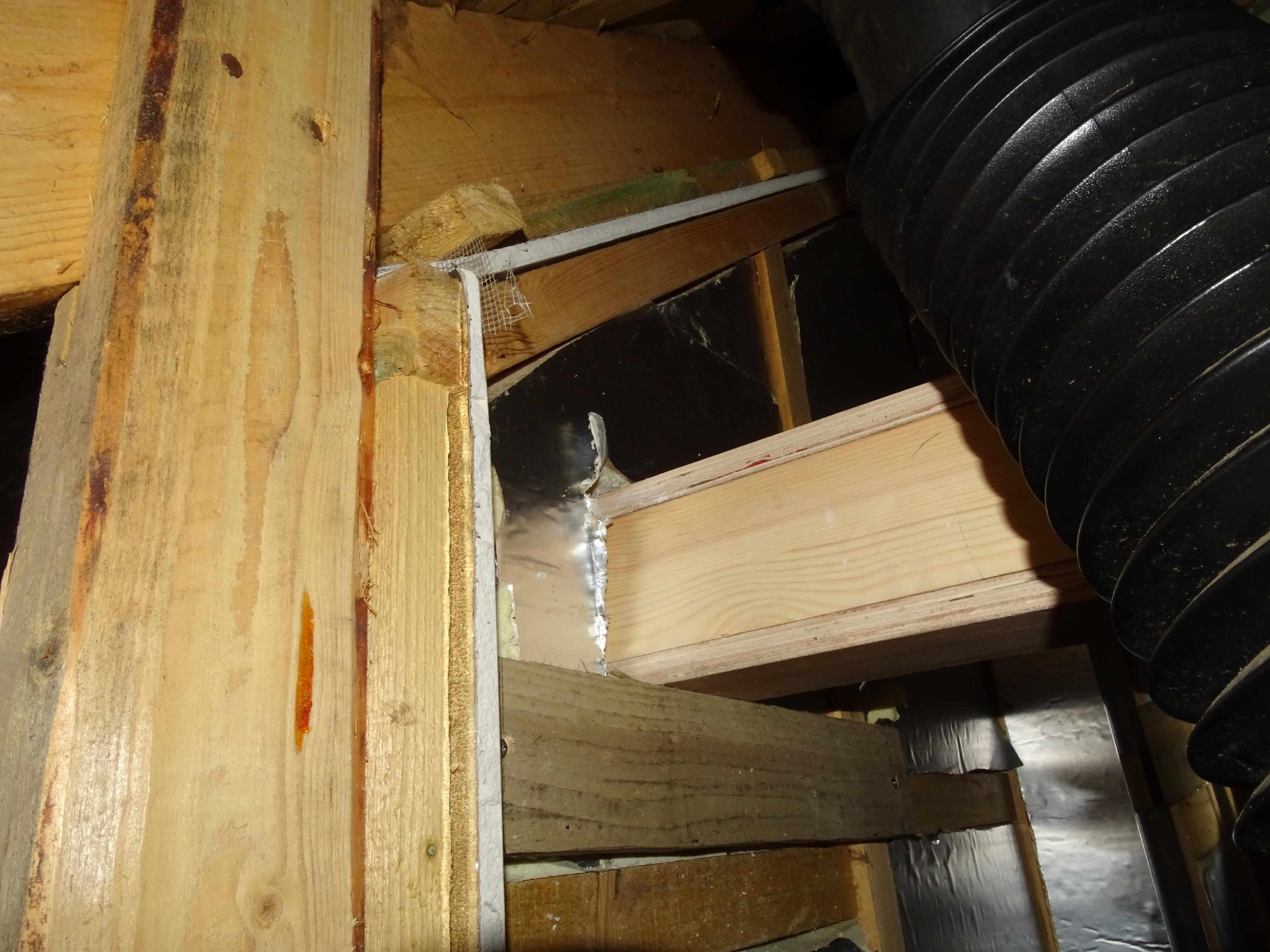
More Roof Space
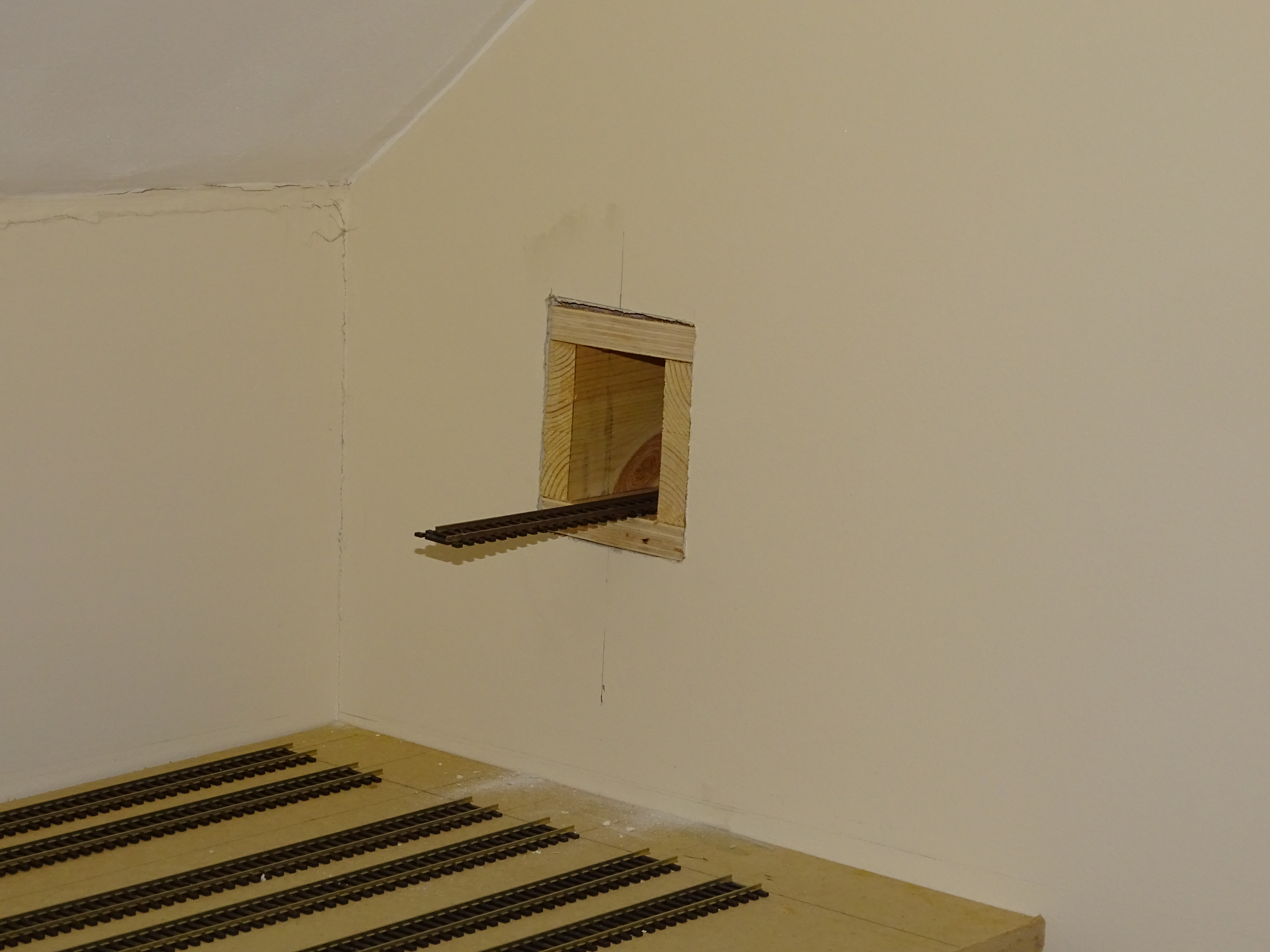
The Tunnel Box fitted - Jump?
As with a lot of my ‘do-it-yourself’ works the gaps were filled with all purpose filler. (What will we do without Wilkinsons?)

Almost Level
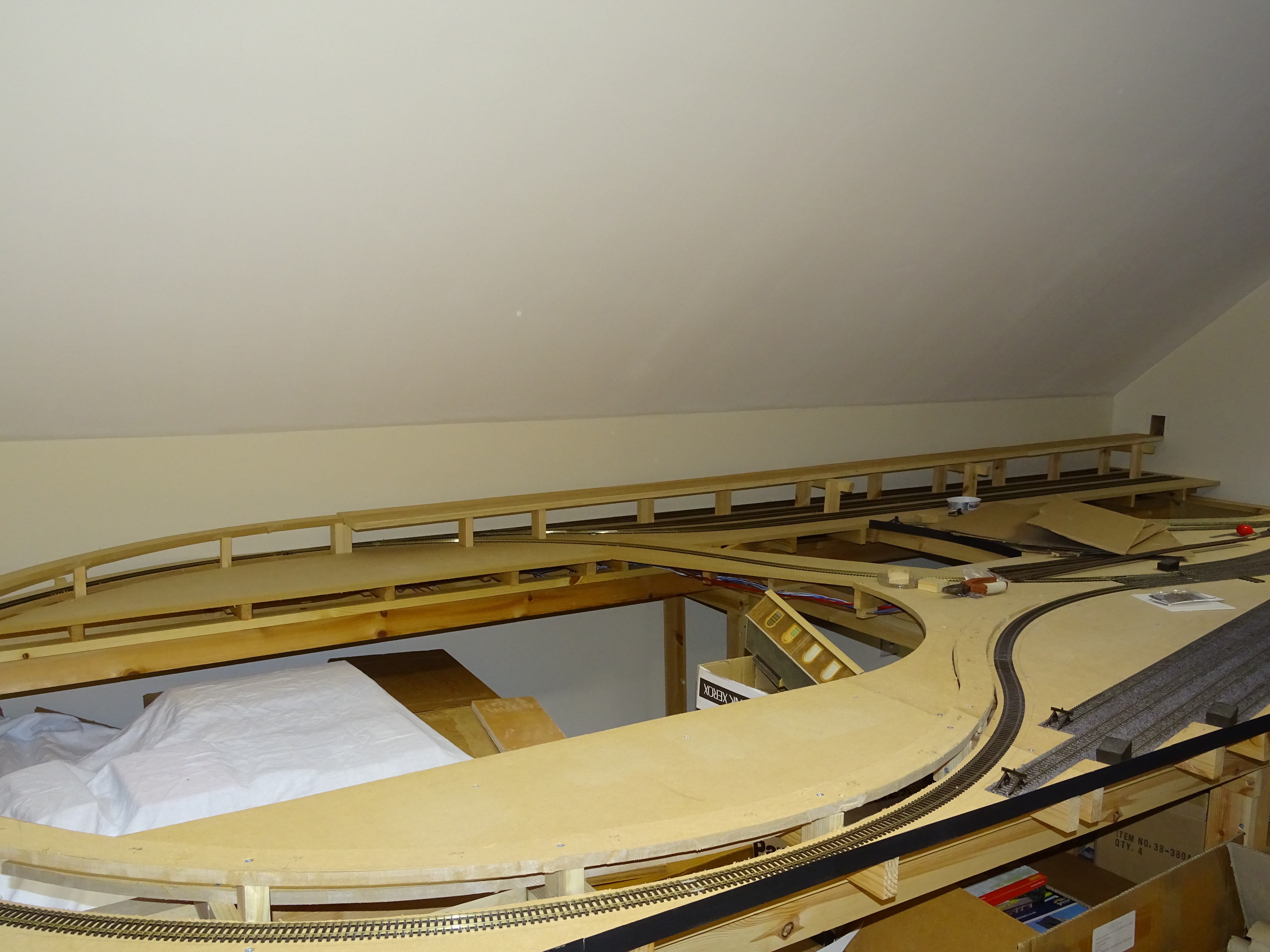
With the tunnel in place all I had to do was construct a ramp up to it (the second tricky bit). As discussed in the previous Post there appeared to be a route around the reversing loop and up over the hidden sidings.

The alignment was marked out and measured. The length from the tunnel mouth down to the connection with the reversing loop was exactly 25feet (300inches)! The height of the entrance to the tunnel mouth above the track bed for the hidden sidings was 5¾ inches. This gave an average gradient of 1 in 52. Experience indicated that whilst not ideal it would be acceptable. Various ‘nay sayers’ have said I should have designed the layout with a flatter gradient. Hindsight is wonderful but sadly as in the real world you have to make do with things as they are. I put together quite a complicated little spread sheet to enable me to calculate the height of the intermediate supports measured from the start of the gradient taking account of the thickness of the fibre board track bed on the curve and the ¾ inch plywood for the straight section.
Out with the jigsaw. For the curved section I used the existing fibre board for the trackbed. For the straight section above the hidden sidings I raided my stash of 3/4inch plywood. Halfway round the curved section I realised that there was sufficient clearance above the lower reversing loop to ease the curve radius


The hidden sidings had been arranged in pairs and in order to make space for supports for the overhead trackwork the last pair of sidings had to be shifted about half an inch outwards.
This done holes were cut through the fibre board surface to locate the cross members and attach new vertical supports.


Some pictures of the completed works. As with most real projects it is always better to have a second go. As planned the lines through the tunnel would simply connect up with the existing station track and attached with nylon rail joiners. Well there is a problem – the nylon joiners offer no support and create a nasty step in the track. The solution second time around was to run a complete yard length of track across the joint and up to the existing station turnout. The nylon joiners were moved to the other end of the yard length and ended up inside the tunnel – not ideal but workable.

The Nylon Rail Joiners as planned

Moving the Rail Joints away from the Tunnel Mouth – a better Solution
Another issue was the connection with the existing trackwork. As planned this would be a single turnout which would require a short section of wrong line running. After an initial play I decided how much better to have a proper junction and the single turnout was replaced with a three points arrangement, negating the need for any wrong line running.


Three Turnouts – no Wrong Line Running
Most of this work was completed in 2021. Since then two tunnel mouths have been created and a halt has appeared. There is a video on YouTube – just hope the driver and fireman have heads for heights.
<a data-flickr-embed="true" href="https://www.flickr.com/photos/longsheds/53322101707/in/dateposted/" title="Rapido 15xx - a birds eye view."><img src="https://live.staticflickr.com/31337/53322101707_b5650033d1_h.jpg" width="1600" height="900" alt="Rapido 15xx - a birds eye view."/></a><script async src="//embedr.flickr.com/assets/client-code.js" charset="utf-8"></script>
Postscript
Early summer and it was hot. The track through the tunnel is not fixed and expanded and moved sideways. The tunnel is quite close to the slates and I would not be surprised if temperatures rose to 40C or more. The track was relaid with larger gaps between individual track lengths.

The perils of ultra hot weather.


Comments