No.50 Keeping in Control – DC Panels and Controller
An outline of the current layout would not be complete
without reference to the controllers and switch panels.
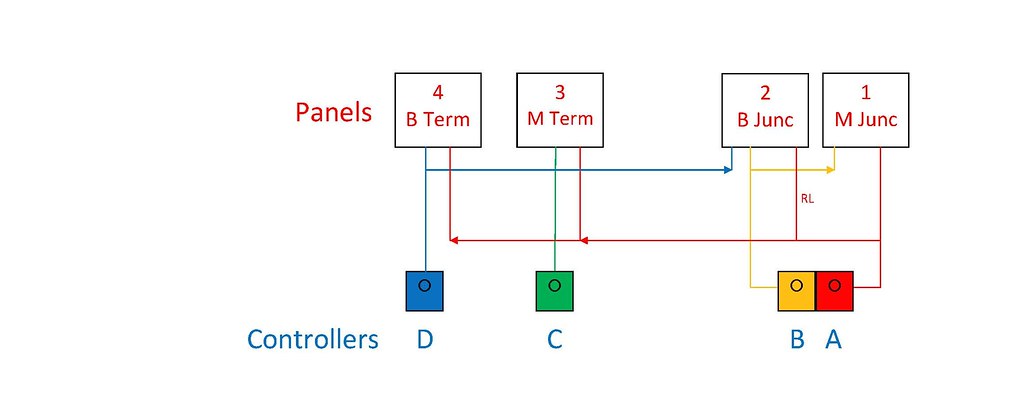
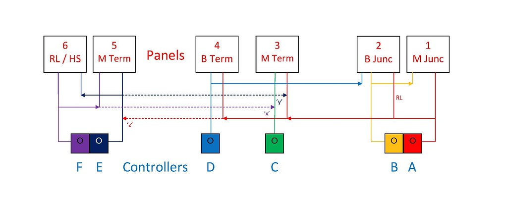
Diagrammatic Controllers and Panels 2005
At the start of construction in 2005 there was a lot of
trackwork and rolling stock from previous incarnations dating back to the
1980s. In 2005 DCC was not considered
and the layout was to be operated by quality Gaugemaster controllers using ‘cab
control’. The diagram above shows the
initial layout of control panels and controllers. Originally it was planned to use Gaugemaster
E and D controllers. However at an early
stage I came across one of Gaugemaster’s inertia controllers with brake
simulation and subsequently two Model P and one Model DS controllers were purchased. The control panels are diagrammatic
representations of the track layout with press buttons (momentary contact) for
point operation, single pole double throw centre off toggle switches for track
sections and single pole single throw toggle switches for isolating
sections. As currently configured the
layout contains 120 points and crossings and the trackwork is divided up into
60 operating sections with a further 58 isolating lengths for loco sheds and
bay platforms.
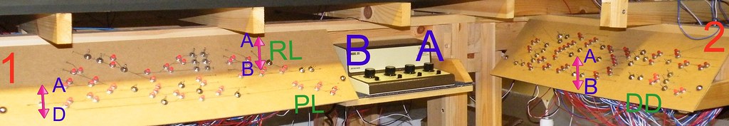 Panels 1 and 2 - the Main and Branch Junctions
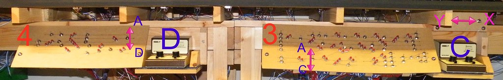
Panels 3 and 4 - the Main and Branch Termini
Controllers A and B provide the power source to Panel No.1 –
the Main Junction and double track continuous run. Controller A is also one of the power sources
for Panel No.2 – the Branch Junction – the second power source for this panel
being Controller D positioned by the Branch Terminus. Controller C provides the power source for Panel
No.3 – the Main Terminus and Controller D provides the power source for Panel
No.4 – the Branch Terminus, for both Panels 3 and 4 the second power source is
provided by Controller A.
My wife was looking over my shoulder at these pictures and
was asking why the controllers appeared to be lettered back to front. My answer is that Controller A is the Main
Controller and is wired through to all four panels and hence was able to
control a train anywhere on the layout.
There is a slight anomaly regarding the Reversing Loop
(labelled RL on Panel No.2). The
Reversing Loop is really part of the double track continuous run and the associated
double pole double throw centre off toggle switches should really have been
located on Panel No.1. However to
optimise the size of the individual panels it was convenient to place the
switches for the Reversing Loop on Panel No.2 powered by both Controllers A and
B.
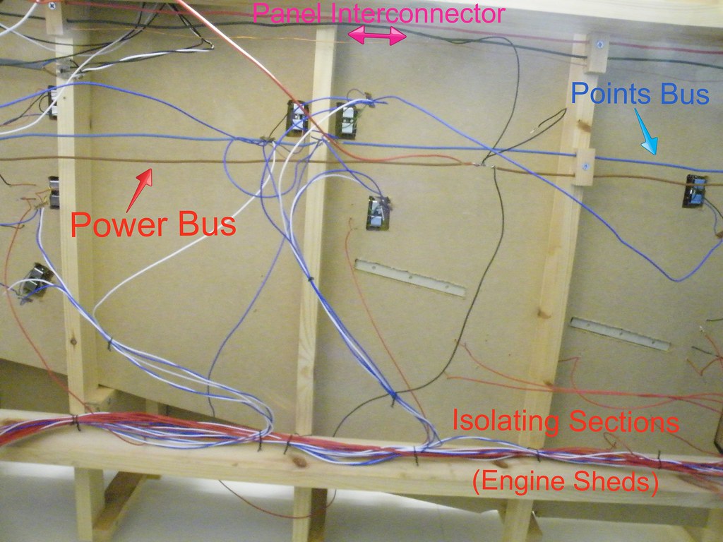
Underside of Baseboards between Control Panels Nos 2 and 3.
The layout uses ‘cab control’ with a common return. Initially all the points were connected to a
common ‘bus’ powered from the AC outlet on Controller B. The view above shows the Blue and Brown cores
taken from household mains cable which form the Points and Power buses
respectively. Also at the top of the
picture there are red, black and copper conductors stripped from another mains
cable (labelled the Panel Interconnector).
The red cable links Controller A with Panel Nos.3 and 4, whilst the
black cable links Controller D (Branch Terminus) with Panel 2. The bare copper wire carries the AC supply from
Controller B to the push buttons on Panel Nos. 3 and 4.
Diagrammatic Controllers and Panels 2012 – with Extension
In 2005 the layout was extended into its present
configuration. The Main Terminus was
converted into a double track through station and a second reversing loop was
added. For control purposes Panel Nos 5
and 6 were added, powered by a second Gaugemaster DS controller (Controllers E
and F).
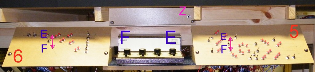
Panels 5 and 6 - the Extension
Panel 5 operates the double track exit from the station
whilst Panel 6 uses double pole double throw centre off switches to operate the
second Reversing Loop and hidden sidings.
The extension is connected to the same Power Bus (common
return) as the rest of the layout.
However the points for the extension are powered separately from a
Points Bus connected to Controller F.
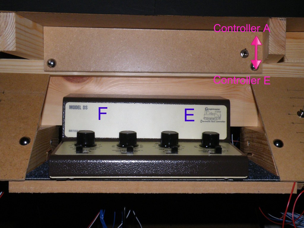
Close up of Controllers E and F showing changeover switch ‘X’
used to connect to Controller A (NB Carpet Tile under Controller to deaden 'Hum')
In order to provide a link between the old and new parts of
the layout the three cores from another mains cable were disassembled. One of the cores was used to bring power from
Controller A (the Main Controller) to the changeover switch labelled ‘X’ which
is used to switch the input to Panels 5 and 6 between Controller A and
Controller E, and hence maintaining the ability of Controller A to operate the
whole layout.
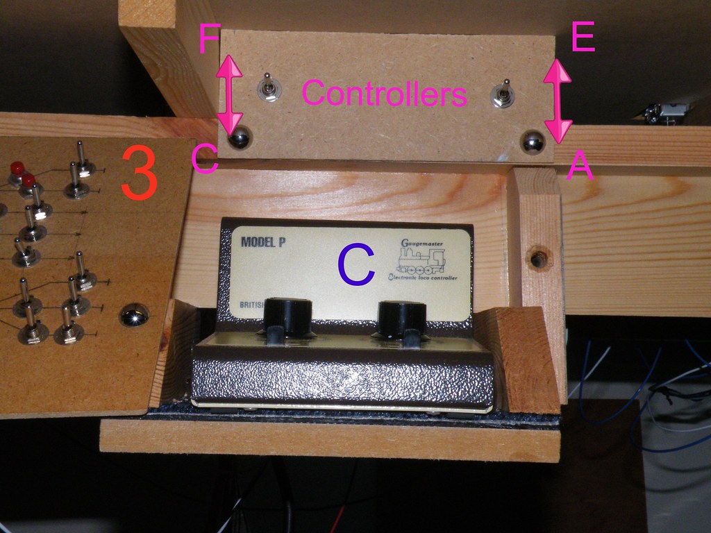
Close up of Controller C showing changeover switches ‘X’ and
‘Y’ used to connect Controllers E and F to Panel No.3
The two other cores from the disassembled mains cable are
used to connect Controllers E and F to changeover switches ‘X’ and ‘Y’
positioned above Controller C explicitly to give Controllers E and F full
control of Panel No.3. By means of these
two toggle switches Controllers E and F can if required operate the complete
Main Terminus / Through Station.
Occasionally I allow my mind to wander and I think about Digital
Control. Quality controllers like the
Gaugemaster DS and P units provide stepless control from zero output – so very
smooth operation. I have a significant
number of steam outline locomotives. In
order to pull a realistic length train up the gradients on this layout I have
had to use the spaces provided for digital control chips to add extra lead
ballast. All my rolling stock has metal
wheels and all the points are Electrofrog.
It is very therapeutic to hear the clickety click of the wheels across
the points. Do I want ‘other sounds’ –
station announcement, engines ticking over, wheels screeching? I suppose the answer is yes, but perhaps all
that is needed is some background noises played through some strategically
placed ‘decent’ speakers. For the moment
‘going digital’ does not seem to offer any benefits – in fact quite the
reverse.


Comments